0
$\begingroup$

My objective is to demodulate the signals with different modulation orders and schemes. In particular, I want to recover the phase first.

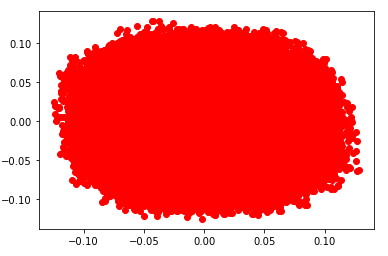
Let us say, my signal looks like in the constellation below

Constellation.

The idea is to position the constellation in such a way that the largest excursions are at 45 degrees angle. In other words, IQ diagram must be shifted by some angle. This angle is determined by the average shift of all points from the reference axis (real or imaginary). The idea itself is coming from this post, where BPSK phase recovery is described.

My problem is that I still do not understand, how do we perform the phase recovery for the higher order modulation schemes. The idea of simply mirroring the constellation to one quadrant (as it works in the case of BPSK) does not seem correct to me and also does not work well. So how we can do it?

Thanks!

$\endgroup$
6
  • $\begingroup$ See this post on using a decision directed phase detector which works well for this application dsp.stackexchange.com/questions/74667/… $\endgroup$ Commented May 8, 2021 at 19:07
  • $\begingroup$ And more specifically this one dsp.stackexchange.com/questions/31497/… $\endgroup$ Commented May 8, 2021 at 19:14
  • $\begingroup$ And this shows the implementation usable for higher order QAM as well as QPSK dsp.stackexchange.com/questions/51856/… $\endgroup$ Commented May 8, 2021 at 19:34
  • $\begingroup$ @DanBoschen thank you for the advice! The concept of PLL is new to me, so I would like to clarify one thing: my approach in demodulating QPSK would be to define the "reference points" on the constellation (+- sqrt(2) +- j sqrt(2)) and then compare all received symbols with them. Then I multiply the received symbol with complex conjugate of the nearest neighbor (reference point) and I obtain the phase that can be used to recover the phase of the symbols. Is this right? $\endgroup$
    – Python
    Commented May 8, 2021 at 20:54
  • $\begingroup$ Yes you have that right- this gives you an error which you should accumulate as the loop filter in the PLL; this is diagrammed in the link I gave above so if something in that link isn’t clear you can ask under that question $\endgroup$ Commented May 8, 2021 at 22:59

1 Answer 1

1
$\begingroup$

This post provides many details on implementing carrier recovery for a higher order QAM system (or even QPSK).

High modulation index PSK - carrier recovery

Using a PI loop filter where in addition to a simple accumulator, a direct (proportional) path is also summed in results in a 2nd order Type 2 tracking loop as required to track phase offsets to zero error under static frequency offset conditions. Symbol-aided synchronization (where a known pilot is used) is recommended for higher order QAM to minimize acquisition time. The coefficients of the loop filter are set to stabilize the carrier recovery loop and also set the appropriate loop BW.

See this post for further considerations on setting the loop BW properly:

Loop bandwidth for symbol timing recovery

$\endgroup$

Your Answer

By clicking “Post Your Answer”, you agree to our terms of service and acknowledge you have read our privacy policy.

Not the answer you're looking for? Browse other questions tagged or ask your own question.