How to recover the carrier of a PSK signal that has high modulation index (eg. 750 symbols per second at carrier frequency 1500 Hz)? I guess that a PLL will not be able to lock onto it with such frequent phase transitions. Maybe upconverting or frequency multiplication of the signal before the PLL is the solution?
-
$\begingroup$ A PLL should be able to handle that just fine. $\endgroup$– JohnCommented Jul 11, 2014 at 13:00
-
3$\begingroup$ Many PLLs are designed to track the double-frequency signal obtained by squaring the input and filtering out the DC term. The double-frequency term does not change phase at the bit transitions and is this a lot easier to track. $\endgroup$– Dilip SarwateCommented Jul 11, 2014 at 13:05
-
$\begingroup$ @Dilip doubling will work for BPSK as 180 x2 = 360 but not for QPSK and higher $\endgroup$– Dan BoschenCommented Mar 1, 2017 at 2:21
-
$\begingroup$ @DanBoschen Yes of course. I was making a comment and wanted to keep it brief, but I am well aware that doubling the frequency will not work for QPSK etc. $\endgroup$– Dilip SarwateCommented Mar 1, 2017 at 2:59
-
$\begingroup$ (@Dilip- I assumed you did! I put the comment mostly for the benefit of others--- I see now that this question and your answer was from years ago...yet it appeared at the top of the question list now, how come??) $\endgroup$– Dan BoschenCommented Mar 1, 2017 at 3:09
2 Answers
A PLL on its own will not work on the direct PSK modulation, assuming the symbols are equi-probable as that results in a nulled carrier, so there is nothing the PLL can track! Costas-Loops are effective for BPSK and QPSK implementations, and as Dilip had suggested, for BPSK you can square your signal and then use a PLL to lock onto the 2F frequency that would come out of the squarer. Why? Because the modulation is going back and for at 0 and 180°, and squaring the signal is a frequency doubler: ($cos(\omega t)^2 = cos(0) +cos(2\omega t)$). When you double the frequency, you also double the phase, so 0° and 180° maps to 0° and 360°, which is the same as 0° and 0° and hence you will have an unmodulated signal to lock onto, you then divide this by two and have a recovered carrier. You can do the same with QPSK but you would need to multiply by 4. Also you must be careful with your selection of loop BW in your carrier tracking loop: If the BW is too wide (competitive with your modulation rate) you will start to track out the modulation! My rule of thumb is to use a carrier tracking loop BW that is 1/20 to 1/100th of the symbol modulation rate. If I need to optimize noise I will start with this and then model my actual implementation since this becomes a trade space with the phase noise in the LO and sampling clock jitter and tracking dynamics desired.
Here are modern all digital carrier recovery implementations that work for all PSK and QAM waveforms, based on detecting phase variation from symbol to symbol and using that to compensate for carrier offsets until the phase change is 0 (delta phase vs delta time = frequency and when 0 we are locked to the carrier):
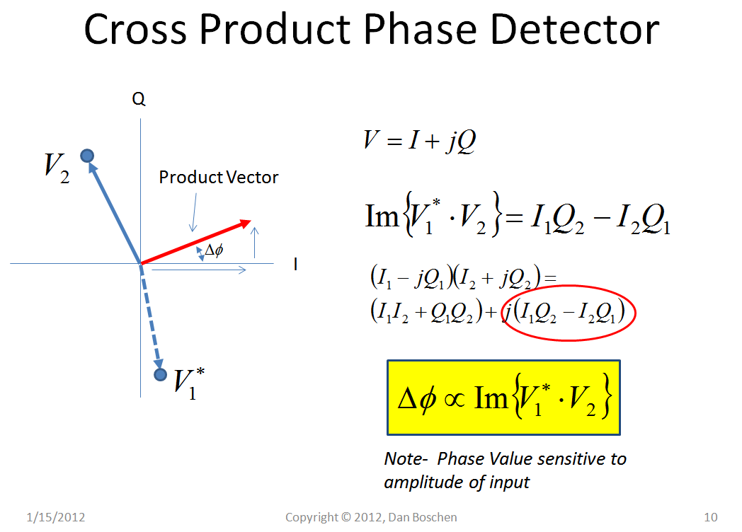
Below shows the "Cross Product Phase Detector" conceptually, showing how taking the complex conjugate multiplication of two vectors results in a vector with a imaginary value that is proportional to the phase of the original two vectors!
This is shown more mathematically below:
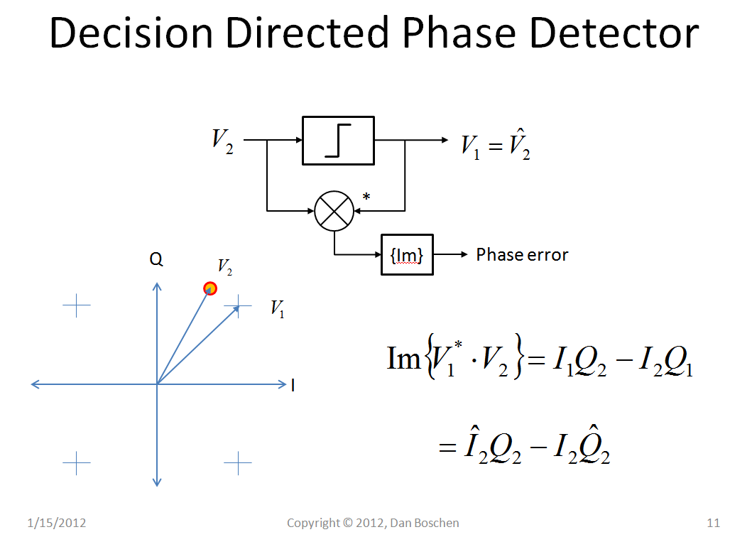
We can use this concept to create a phase detector that can act directly on the modulated signal, such as the Decision Directed Phase Detector shown in the image below. The cross hairs are the "decisions" to be made on each sample, choosing the closest constellation point (in this example QPSK), and the decided vector is complex conjugate multiplied with the vector prior to the decision, and the result is an error signal that is proportional to the phase error!
Since V1 and V2 in the image above are complex signals with I and Q, we can redraw that same implementation as in the figure below, which is the Costas Loop for a QPSK modulation!
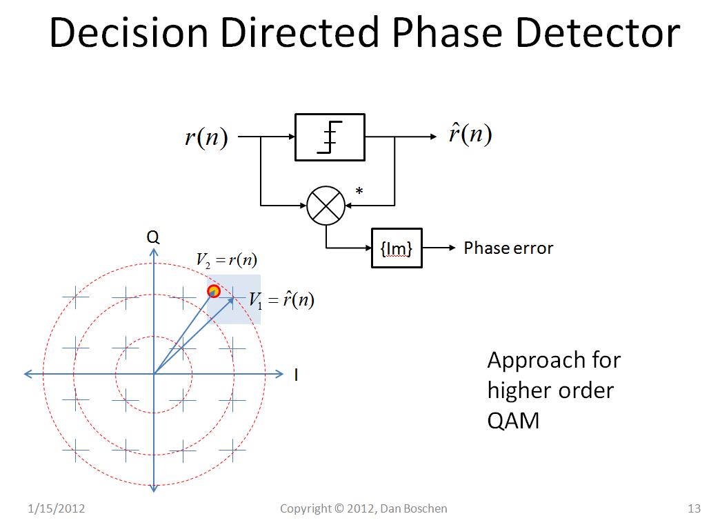
Just add more decision thresholds and you can demodulate higher orders of modulation such as the QAM implementation below!
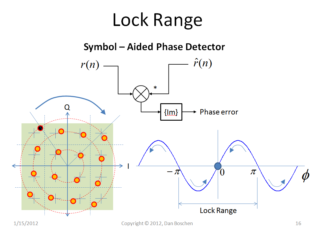
Of course the "lock range" is reduced as the order gets higher:
The lock range can be enhanced by using a "Symbol Aided Phase Detector" which is a common approach for acquisition where known data symbols are transmitted for channel estimation and initial capture of carrier phase and timing. Once acquired the previous methods shown can readily continue to track the carrier with random data symbols.
Below this gets all tied together showing a Decision Directed Carrier Recovery Loop as an all digital carrier tracking implementation and provides the final I Q decisions (demodulated symbols). The complete receiver would also have channel selection, AGC, equalization, timing recovery and matched filtering prior to this:


