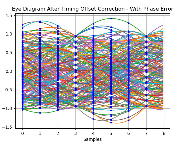
My objective is to demodulate QPSK signal. At the receiver I apply RRC filter and interpolate the signal to get the values of the signal (approximately) at the sampling instances. Then I am concerned with the symbol timing recovery to get the correct sampling timing. The filtered and interpolated signal is represented in the figure below.
Red vertical lines indicate the symbol intervals. Obviously, the symbol timing recovery is needed. My idea is to apply PLL in order to track the phase error to zero and then sample the corrected signal at correct time instances.
So I have the following python code:
import pdb

class SimPLL(object):
    def __init__(self, lf_bandwidth):
        self.phase_out = 0.0
        self.freq_out = 20*pow(10, 6)  # Arbitrarily set, because I expect to get the input signal in the range of 20 MHz. Thus with this frequency I think the PLL can be locked faster
        self.vco = np.exp(1j*self.phase_out)
        self.phase_difference = 0.0
        self.bw = lf_bandwidth
        self.beta = np.sqrt(lf_bandwidth)

    def update_phase_estimate(self):
        self.vco = np.exp(1j*self.phase_out)

    def update_phase_difference(self, in_sig):
        self.phase_difference = np.angle(in_sig*np.conj(self.vco))

    def step(self, in_sig):
        # Takes an instantaneous sample of a signal and updates the PLL's inner state
        self.update_phase_difference(in_sig)
        self.freq_out += self.bw * self.phase_difference
        self.phase_out += self.beta * self.phase_difference + self.freq_out
        self.update_phase_estimate()
pll = SimPLL(f_symb//20) # I have read in one post, that with the bandwidth of the loop filter between f_symb/100...f_symb/20 PLL performs well
num_samples = 100
phi = 0
ref = []
out = []
diff = []
for i in range(0, num_samples - 1):
    in_sig = sig_interpolated[i]
    phi = np.angle(sig_interpolated[i])
    pll.step(sig_interpolated[i])
    ref.append(sig_interpolated[i])
    out.append(pll.vco)
    diff.append(pll.phase_difference)
#plt.plot(ref)
#plt.plot(ref)
#plt.plot(out)
#plt.plot(diff)

ref, = plt.plot(ref, label='ref')
out, = plt.plot(out, label='out')
diff, = plt.plot(diff, label='diff')

plt.legend(handles = [ref, out, diff], loc = 'upper right')

plt.show()
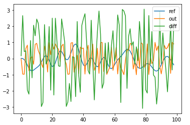
And the result I get is represented in the figure below:
So it seems like the PLL cannot lock the loop and the signal cannot be corrected.
Does anybody know, how to fix my code or can point me to the relevant example?
Thanks!


rrc_impulse_response = rrcosfilter(10, 0.22, 1/f_symb, Fs)[1], sig_filtered = np.convolve(sig, rrc_impulse_response)I know that roll off factor = 0.22 at transmitter, so I set the same one at the receiver. The length of the filter - I do not understand quite well how to select, so I try different values and in this case it was 10. So do you think there is still problem with filtering or I can already work on symbol timing recovery right now? $\endgroup$