1
$\begingroup$

I've been playing around with using a PLL for phase demodulation and it's working pretty well. The PLL locks to the carrier and the error term is the demodulated message signal. However, depending on what the underlying message signal is, it is sometimes necessary to configure the PLL to have a very small loop bandwidth - the effect is to prevent the PLL's internal state to respond too quickly to deviations caused by the message signal.

On the otherhand, it's very useful for the PLL to automatically handle locking to the carrier at an offset frequency and/or track doppler - in this situation, a larger loop bandwidth is essential.

With this in mind - is it a valid approach to have a PLL with a default acquisition mode with a large loop bandwidth, and then once lock is detected, transition to a smaller loop bandwidth to give good phase demodulation performance? One idea I had for this is computing the frequency estimates via the loop's phase (e.g. $f_{loop}[n] = \phi_{loop}[n] - \phi_{loop}[n-1]$) vs the detected input sample phase ($f_{i}[n] = \phi_{in}[n] - \phi_{in}[n-1] $), if these are about the same (after averaging/lpf) the loop would be considered locked and the bandwidth reduced.

Are there any well known/used approaches to take in this problem - (solutions beyond the single PLL are welcomed too).

thanks.

$\endgroup$

1 Answer 1

2
$\begingroup$

Yes this is very common to have a dynamic loop bandwidth such that during acquisition the loop bandwidth is wider, and then once acquired to tighten it up for better noise performance.

A typical loop will have an error signal determined which is presented to the input of the loop filter. The filtered version of this error signal can be thresholded and used as a lock determination metric. The loop must also be designed such that the loop bandwidth can be transitioned from wide to narrow without disrupting the lock state.

Note that even after acquisition you would like the loop bandwidth to be as wide as possible depending on the dynamics of the link (you mention Doppler, of interest after acquisition would be the maximum possible rate of change of the Doppler offset), but you don't want it so wide that it starts to track out the phase variation inherent in the modulation itself. The phase noise of your local oscillator (LO) plays a big part too in optimizing this loop bandwidth for carrier tracking; if you make the loop bandwidth too tight then your LO and similar jitter sources (ADC clock) start contribution to your noise in detrimental ways.

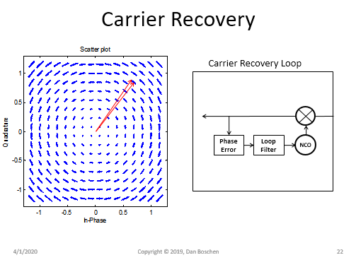
To this point consider the plot below showing the effect of local oscillator phase noise on a QAM signal and how it interacts with a carrier recovery loop:

carrier recovery QAM

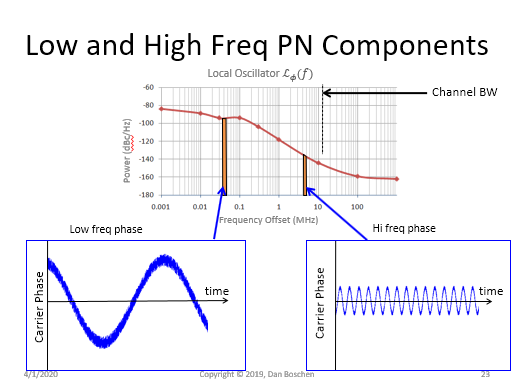
Consider two "slices" from the phase noise spectral density for an example oscillator:

LO

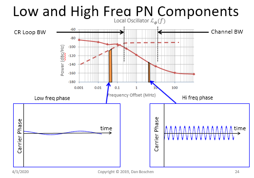
The carrier tracking loop is a high pass filter to these noise contributions; the the lower frequency phase noise contribution (which has a significantly higher noise level if not filtered) is significantly effected by the carrier tracking loop bandwidth.

enter image description here

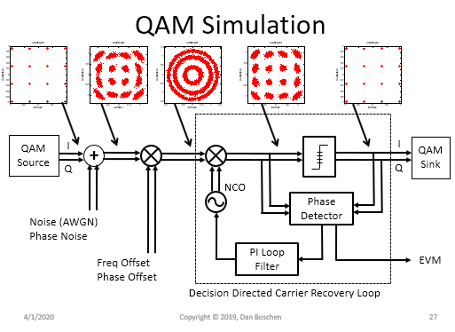
Here is the result of a simulation I had done where you can see how the phase noise contribution is reduced from the rejection provided by the (higher) carrier tracking loop bandwidth.

QAM Simulation

I wanted to hammer this point home since your question implied that a lower loop bandwidth is a lower noise result and it's actually a minimization problem between LO phase noise/ clock jitter, and carrier loop tracking noise (and signal removal from tracking out the signal).

I go into more detail of this at this post:

Loop bandwidth for symbol timing recovery

$\endgroup$
3
  • $\begingroup$ Nice answer Dan thanks. Do you have any pointers to reference sources on the design of loops that can handle variation of the loop bandwidth parameters without losing lock - or any specific search terms on this? $\endgroup$
    – user67081
    Commented Apr 2, 2020 at 22:00
  • $\begingroup$ Simply pay close attention to how you change the loop bandwidth in your design such that you don't create a step in the control output of the loop filter when you make the bandwidth change. In the design such as the one I show above, the bandwidth is controlled by the gain coefficients in the PI loop filter- I can anticipate many ways in which I could change those parameters without causing an abrupt discontinuity (such as ramping bewteen values if necessary). $\endgroup$ Commented Apr 3, 2020 at 16:14
  • $\begingroup$ Yep that makes sense. I found another technique in the literature I believe called "gear shifting" whereby a new set of PI parameters is loaded and a compensation term is added to avoid such discontinuities. $\endgroup$
    – user67081
    Commented Apr 4, 2020 at 6:11

Your Answer

By clicking “Post Your Answer”, you agree to our terms of service and acknowledge you have read our privacy policy.

Not the answer you're looking for? Browse other questions tagged or ask your own question.