2
$\begingroup$

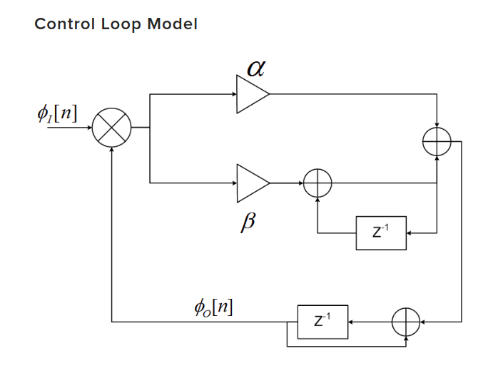
I'm currently working with BPSK carrier phase and frequency recovery in GNU Radio. I have been able to use Costas loop and Frequency locked loop (four carrier acquisition) which are based on the control_loop class (this class implements a PLL). Until now, I never needed to configure the control_loop class since the wrapper classes (Costas and FLL) do this by default. As it can be seen below, the control loop (PLL) is based on the proportional-plus-integrator. The control loop constructor takes three variables control_loop(loop_bw, max_freq, min_freq). max_ and min_freq variables are used to keep the frequency (in the integrator part of the loop) between max_freq and min_freq. I have looked into the Costas and FLL source code and saw how they are configured.

Let's start with Costas loop.

  1. The loop is configured to have max_freq/min_freq of +1 and -1 respectively
  2. The phase error input to the control loop i.e. (Φ_i[n] - Φ_o[n]) is bound between -1 and 1.
  3. After the phase error has been filtered, the output phase i.e. Φ_o[n] is wrapped (between 2pi and -2pi). The frequency is forced into the max_freq and min_freq [1,-1] region.

With the FLL,

  1. The loop is configured to have max_freq/min_freq of (2*PI/samples_per_symbol) and -(2*PI/samples_per_symbol) respectively.
  2. Unlike the Costas loop, the phase error input to the control loop i.e. Φ_i[n] is not bounded.
  3. Like the Costas, the output phase i.e. Φ_o[n] is wrapped (between 2pi and -2pi). The frequency is forced into the max_freq/min_freq of (2*PI/samples_per_symbol) and -(2*PI/samples_per_symbol) region.

I basically have three questions

  1. Why is the input phase error of the Costas loop limited in the [1,-1] region?
  2. How do you choose the frequency region [max_freq and min_freq] of the integrator part of the loop? why do we need to limit the frequency range?
  3. Why is the output phase Φ_o[n] (in both Costas and FLL) wrapped between -2PI and 2PI?

I have added links to the source code of the Costas and the FLL blocks

  1. Costas Loop: https://github.com/gnuradio/gnuradio/blob/master/gr-digital/lib/costas_loop_cc_impl.cc
  2. FLL band-edge : https://github.com/gnuradio/gnuradio/blob/master/gr-digital/lib/fll_band_edge_cc_impl.cc

Regards, M.

control loop

$\endgroup$
2
  • 1
    $\begingroup$ i think you will need to provide a bit more justification of the premises to your questions. it's just like they came outa the air. BTW, while this Control Loop Model of a PLL looks correct, remember that, implicitly $\phi_I[n]$ and $\phi_O[n]$, the phases of the input waveform and output oscillator (an NCO) are incrementing forever (not wrapped) because the frequencies are always positive. but the phase difference, which is $\phi_I[n] - \phi_O[n]$ is being controlled by the controller and should be bounded. $\endgroup$ Commented Jul 13, 2018 at 17:44
  • $\begingroup$ @robertbristow-johnson The PLL block diagram (in relation to the source code) is a bit confusing. But you are absolutely right. The bounded error is (Φ_i[n] - Φ_o[n]), and not the input phase. I'm not sure how to answer about the justification for these questions. Basically, I want to understand why the frequency of the integrator part of the loop filter is bound by the values I mentioned. Once I understand this, I will be able to proceed to the implementation of higher order PLLs (up to 4th). I have added a list of links to the source codes of the Costas and FLL blocks. $\endgroup$ Commented Jul 13, 2018 at 18:43

1 Answer 1

3
$\begingroup$

Before I address your questions, you should understand:

a. the integral branch of the loop filter maintains a average phase increment in units of radians/sample. It is not a frequency value, though in the right context it can be converted to a frequency value, using your sample rate as a conversion factor.

b. the total output of the loop filter is an instantaneous phase increment which is used to advance the numerically controlled oscillator's phase.

So to your questions:

  1. Why is the input phase error of the Costas loop limited in the [1,-1] region?

It looks like an arbitrary limit to keep the instantaneous phase increment output of the loop filter to some sane number of radians/sample. (Correcting more than $\pm\pi$ radians/sample is pointless.)

The average phase increment maintained by the integral branch is limited to $\pm 1.0$ radians/sample as well. In a no-signal, noise processing situation, the integrator output can grow without bound, so the limiters are needed. The $\pm 1.0$ radians/sample is just an arbitrary limit to keep the loop near sane operating values for when a signal does come in. A Costas loop that is applying a correction of more than 1 radian/sample is probably not anywhere near converged anyway.

  1. How do you choose the frequency region [max_freq and min_freq] of the integrator part of the loop? why do we need to limit the frequency range?

In your application context, which you really haven't provided, you have to decide what are reasonable limits for the average phase increment coming out of the integrator. You must provide limits, because the integrator is unstable and its output can grow without bound, which would make the PLL useless.

For a Costas loop, the spacing in radians of your constellation points and the number of samples/symbols will dictate what are sensible limits for the maximum & minimum increment of the NCO in radians for each sample processed. Anything outside of the interval $(-\pi, \pi)$ radians/sample would be nonsensical due to phase wrapping.

For a PLL that is trying to lock on to a tone in a particular frequency range $[f_{low}, f_{high}]$ in Hz, you can use your sample rate, $F_s$, to convert those to limits in units of radians/sample, i.e. $\left[\dfrac{\pi f_{low}}{F_s/2},\dfrac{\pi f_{high}}{F_s/2}\right]$ radians/sample.

  1. Why is the output phase Φ_o[n] (in both Costas and FLL) wrapped between -2PI and 2PI?

Because computation of $e^{j\phi_o}$, used for setting the NCO output, is generally numerically better with smaller angle arguments in most libraries. Phase is cyclic so it's OK to just wrap down to small magnitude angles.

$\endgroup$
1
  • $\begingroup$ This solves all the doubts I had. Thanks, @AndyWalls. Just out of curiosity, for the case of the FLL, after conversion from rad/sample to Hz, the frequency is allowed to "wander" between $\pm 2R_{s}$. Isn't that too far off? $\endgroup$ Commented Jul 16, 2018 at 14:27

Your Answer

By clicking “Post Your Answer”, you agree to our terms of service and acknowledge you have read our privacy policy.

Not the answer you're looking for? Browse other questions tagged or ask your own question.