I'm trying to implement a digital IIR filter on an FPGA and would be happy for some inputs regarding the actual digital implementation. I don't have a lot of experience with FPGAs and digital filters in general and this whole matter seems more difficult than I first expected it to be, especially things like required bitwidths, rounding error/coefficient quantization and saturation. The system uses a Zynq xc7z030 FPGA (speed grade 3) and a clock frequency of 125 MHz (the datarate is 125 MSPS).
I started by looking for a suitable filter design using Matlab's "filter designer". I don't have "hard" specifications (just want to get rid of some noise which occurs around 10 MHz), so I decided to use a 2nd order butterworth filter with a corner frequency of 5 MHz as a first attempt. The resulting coefficients I obtained are:
[b0 b1 b2] = [13.3592e-003 26.7184e-003 13.3592e-003] [a0 a1 a2] = [1.0000e+000 -1.6475e+000 700.8968e-003]
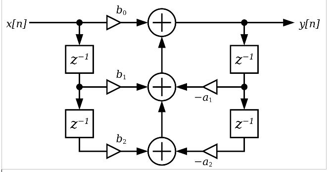
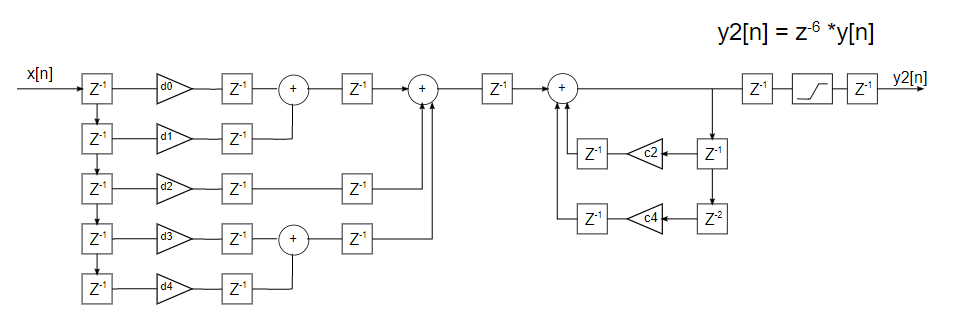
I know that there is different filter structures (Direct form I and II and their transposed versions) to implement this. The problem I face here is timing: I observed that I can only fit two numerical operations (addition or multiplication) into a 8 ns clock period. However, all of those structures usually have more than two additions in series, making it impossible to meet timing (e.g. see here: https://ccrma.stanford.edu/~jos/fp/Direct_Form_I.html) and I can't do pipelining in the all pole part since my a1 coefficient is nonzero. I therefore came up with the structure in the attached picture.
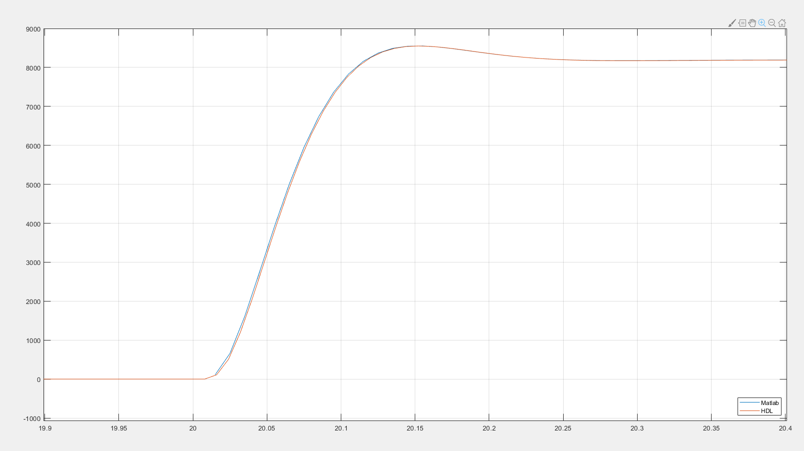
I than implemented the filter in VHDL and simulated it. The result is actually quite promising and seems to work fine.
The actual questions I have now are:
- What filter structure would you use for such a filter and why? Is the one I implemented suitable or would you recommend something else? Would it make a difference if I swap the order of the all zero and all pole part?
- My input and output is 16 bits and I used 25 bit to quantize the coefficients because the DSP slices of the Zynq have 25 bit multipliers. For the internal quantities I used 24 bits. The reason for this 24 bits is a little bit arbitrary: I did a bodeplot and a step response of the all pole part and saw that its peak gain is 25.4 dB and the step response has an overshoot up to 19.6. To cover this, my filter internals need 5 bits more than my input -> 21 bits. I added 3 more to be on the save side. How would you properly determine the required bitwidth for the internal quantities? Is there some way to guarantee that no overflow will occur? From the simulations it seems to work, but I'd like to be sure that there is no input signal I'm not aware of which could cause an overflow.
- The coefficients have 23 fractional bits, multiplication is done by multiplying the 25 bits and right shifting the result 23 times. Afterwards, rounding is done by just truncating the last 25 bits. I know that this is not the best way to round the results. How would this be properly done, especially when I have to meet the timing requirements (only one multiplication + one addition allowed in the feedback path)?
- Any other remarks or things I overlook here?
VHDL code:
library ieee;
use ieee.std_logic_1164.all;
use ieee.std_logic_unsigned.all;
use ieee.numeric_std.all;

entity IIR2OrderFilter is
    port (
        Clk           : in std_logic;         -- Clock
        Rst           : in std_logic;         -- Reset
        InData        : in std_logic_vector(15 downto 0);   -- Data input
        DataOut       : out std_logic_vector(15 downto 0)   -- Data output

    );
end entity IIR2OrderFilter;

architecture behav of IIR2OrderFilter is

Constant C_POLE_COEFF_WIDTH                      : Integer := 25;
Constant C_POLE_SCALE_FACTOR_NUMBIT              : Integer := 23;

Constant C_ZERO_COEFF_WIDTH                      : Integer := 25;
Constant C_ZERO_SCALE_FACTOR_NUMBIT              : Integer := 23;

Constant C_POLE_INTERNAL_BITWIDTH                : Integer := 24;

Constant C_ZERO_INTERNAL_BITWIDTH                : Integer := 24;

Constant CoeffB0                            : Integer := 112065;
Constant CoeffB1                            : Integer := 224130;
Constant CoeffB2                            : Integer := 112065;
-- Constant CoeffA0                         : Integer := ;
Constant CoeffA1                            : Integer := 13819896;
Constant CoeffA2                            : Integer := -5879548;


signal AccuxDN, AccuxDP                     : signed(C_POLE_INTERNAL_BITWIDTH-1 downto 0);
signal AccuPreSum                           : signed(C_POLE_INTERNAL_BITWIDTH-1 downto 0);

signal AccuA1                               : signed(C_POLE_INTERNAL_BITWIDTH-1 downto 0);
signal AccuA2, AccuA2Del                    : signed(C_POLE_INTERNAL_BITWIDTH-1 downto 0);
signal AccuB0                               : signed(C_ZERO_INTERNAL_BITWIDTH-1 downto 0);
signal AccuB1                               : signed(C_ZERO_INTERNAL_BITWIDTH-1 downto 0);
signal AccuB2, AccuB2Del                    : signed(C_ZERO_INTERNAL_BITWIDTH-1 downto 0);

signal AccuB1B2Sum                          : signed(C_ZERO_INTERNAL_BITWIDTH-1 downto 0);
signal AccuB1B2SumDel                       : signed(C_ZERO_INTERNAL_BITWIDTH-1 downto 0);
signal AccuB0B1B2Sum                        : signed(C_ZERO_INTERNAL_BITWIDTH-1 downto 0);


begin


AccuPreSum <= AccuA2Del + signed(InData);
AccuxDN <= AccuPreSum + AccuA1;


IIRRegs: process (Clk)
begin
if rising_edge(Clk) then
    if Rst = '0' then
        AccuxDP <= (others => '0');
        AccuA2Del <= (others => '0');
    else
        AccuxDP <= AccuxDN;
        AccuA2Del <= AccuA2;
    end if;
end if;
end process IIRRegs;

AccuA1 <= resize(shift_right(AccuxDP * to_signed(CoeffA1, C_POLE_COEFF_WIDTH), C_POLE_SCALE_FACTOR_NUMBIT), C_POLE_INTERNAL_BITWIDTH);
AccuA2 <= resize(shift_right(AccuxDP * to_signed(CoeffA2, C_POLE_COEFF_WIDTH), C_POLE_SCALE_FACTOR_NUMBIT), C_POLE_INTERNAL_BITWIDTH);

AccuB0 <= resize(shift_right(AccuxDP * to_signed(CoeffB0, C_ZERO_COEFF_WIDTH), C_ZERO_SCALE_FACTOR_NUMBIT), C_ZERO_INTERNAL_BITWIDTH);
AccuB1 <= resize(shift_right(AccuxDP * to_signed(CoeffB1, C_ZERO_COEFF_WIDTH), C_ZERO_SCALE_FACTOR_NUMBIT), C_ZERO_INTERNAL_BITWIDTH);
AccuB2 <= resize(shift_right(AccuxDP * to_signed(CoeffB2, C_ZERO_COEFF_WIDTH), C_ZERO_SCALE_FACTOR_NUMBIT), C_ZERO_INTERNAL_BITWIDTH);


AccuB1B2Sum <= AccuB2Del + AccuB1;
AccuB0B1B2Sum <= AccuB1B2SumDel + AccuB0;


FIRRegs: process(Clk)
begin
if rising_edge(Clk) then
    if Rst = '0' then
        AccuB2Del <= (others => '0');
        AccuB1B2SumDel <= (others => '0');
        DataOut <= (others => '0');
    else
        AccuB2Del <= AccuB2;
        AccuB1B2SumDel <= AccuB1B2Sum;
        DataOut <= std_logic_vector(resize(AccuB0B1B2Sum, 16));
    end if;
end if;
end process FIRRegs;


end architecture behav;


