Below provides detailed design approaches specific to sampling a real passband. Please also see this other post that already details the related information for the case of a real baseband signal, and this post that details further the effects of oversampling that would also be considered.
Bottom Line:
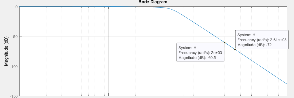
You cannot sample a signal that occupies out to 500 Hz with only 1 KHz sampling and expect to eliminate the aliasing from the 2nd Nyquist zone (that would require a brick-wall filter). A transition band should be allowed for by sampling at some frequency higher than twice 500 Hz -- the higher the frequency the simpler the filter is to implement.
The rejection required depends on SNR requirements for the signal and what else may be occupying the portion of the spectrum in the stop band to be filtered out (is it simply an extension of the noise floor in band, or is there interference or other signals to separate from?).
Below details this further specific to this challenge for a radio design, and the principles used would be applicable to the sampling of any signal when we are ultimately concerned with the signal to noise of the sampled signal. I show below a case of how 10 dB stopband rejection can be more than sufficient, and the conditions that would exist where we would need to increase that rejection.
Details:
First with a practical 12 bit ADC you likely will not have 12 actual bits of resolution. The datasheet will provide an "ENOB" (Effective Number of Bits, or Equivalent Number of Bits) which capture internal noise and non-linearity effects based on the actual SNR achieved (under specific conditions of sampling rate and the frequency of a single tone characterized, at a specific back-off from full scale, typically 1 to 2 dB-- all of these will effect ENOB). With a known SNR, the ENOB is determined from the formula for SNR of a full scale sine wave:
$$SNR=6.02 \text{ dB/bit} + 1.76 \text{ dB}$$
(There is no good reason to keep that formula out to two decimal places but it is how it is most often seen: 6 dB/bit + 1.8 dB would be fine!).
Second, you do not need 72 dB of attenuation at the Nyquist Frequency, but sufficient attenuation to reduce the noise density from aliasing to be lower than the noise density within the bandwidth of the waveform being sampled (which is often less than Nyquist, simplifying that anti-alias filter). For this we will need some margin between the boundary of the frequency of interest and Nyquist to allow for a transition frequency for implementing realistic filters.
See the example below showing a case where 10 dB stop band rejection would be more than enough if we didn't have interfering signals or adjacent channels. Ultimately what we want is for the noise density from each higher Nyquist zone that will fold in during sampling to be more the X dB below the original noise density in band- and if designed right, this noise floor should NOT be the ADC quantization noise, but amplified noise from the front end of the analog receiver with equally minimized contributions from our electronics with similar considerations (this is what we want to sample for a well designed radio and not our own self-noise!). If there are other signals present, they will be part of that noise density in which case the rejection must be large enough to eliminate them. If there are no other signals present and it is just the same noise floor, then not nearly as much rejection is needed. Since the noise in each Nyquist band is independent, each of these contributions will sum in power (sum squared). For that we need to consider the wider band spectrum being sampled as it appears after the anti-alias filter, as well as the analog input bandwidth of the ADC.
With that, the total degradation in SNR, which is the increase in Noise Figure is given according to a simple power summation as:
$$NF_\Delta = 10Log_{10}(1+10^{X/10})$$
For instance, if we were to keep the total noise contribution 10 dB below our original noise floor, the noise figure degradation would be 0.4 dB. If the total folded noise was equal to our original noise floor, the noise floor degradation would be 3 dB or 1/2 a bit.
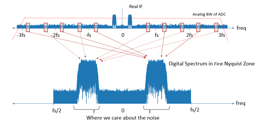
Below provides a practical example showing what would occur if we didn't provide any additional anti-alias filtering for an ADC sampled at a rate that is 1/3 of it's own analog input bandwidth (which can be determined from the datasheet for the ADC). In this case we are confident that there are no other interfering signals within this bandwidth, which is an unlikely (and often bad) assumption, and the noise floor is the amplified thermal noise in the receiver up to the input of the ADC. We are sampling a real waveform at 6 times its occupied BW. What we see from this, that there are 5 additional Nyquist zones that are being folded in within the total analog bandwidth shown. This means the noise floor within our bandwidth of interest will have increased by $10log_{10}(5) = 7$ dB and we would have lost over 1 bit of effective ADC resolution.

We note from the 6x oversampling of the passband bandwidth that the total quantization noise is spread over 3 times the occupied bandwidth from our signal, so assuming we have sufficient spurious-free dynamic range in the ADC (another spec from the datasheet), we get an additional $10log_{10}(3) = 4.8$ dB SNR from our higher sampling rate.
Tying this all together
So with all that in mind, if I wanted to make the effect of aliasing negligible, I would also assume that I want to make the effect of quantization noise negligible. Which means the quantization noise itself needs to be below the amplified noise that we receive at the antenna input. This defines how much front-end gain we need. For all this I would need to give an actual budgetary value to "negligible". For example, if we use a total allowable degradation of 0.4 dB SNR, (this means a 0.4 dB increase to noise figure from this part of the design), this would be a total noise contribution of 10 dB below the amplified analog noise floor as given by the formula presented above. We may ask why not make this 20 dB which would result in only a 0.04 dB degradation? What we lose by making this larger is overall dynamic range - meaning the ability to handle very large signals including interference/ jamming.
Let's assume we used 15 dB as the limit of each individual contribution, and for convenience let's assume "full scale sine wave" is +10 dBm (1-2 dB below actual clipping as given in the ADC datasheet for best spurious free dynamic range and ENOB). Then we will have amplified the received signal to be 15 dB above the quantization noise floor (and immediately get a noise figure increase of $10\log10(1+10^{-15/10})= 0.135$ dB. If we had a 12 bit ADC with a 10.5 dB ENOB (this would be typical), and oversampled a real IF waveform by the factor of 6 as above, then our total noise in band due to quantization noise, relative to what a "full scale sine-wave" would be at the ADC input, will be $(6.02)(10.5)+1.76 + 10Log_{10}(3)= 69.74$ dB lower than that reference level given by a sine wave at full scale or -59.74 dBm (total power within our signal bandwidth, not noise density which is given as dBm/Hz). Given the 15 dB target, our receiver gain would need to place thermal noise + receiver noise figure 15 dB above this, such that the noise floor in band is -44.74 dBm prior to adding quantization noise, and -44.74 + 0.135 = -44.61 dBm including the quantization noise. If we didn't provide any additional anti-alias filtering (and the noise was flat out to the analog input bandwidth of the ADC), we would effectively increase the quantization noise contribution by 7.0 dB as introduced above.This means instead of adding uncorrelated noise that is 15 dB below the received and amplified noise floor, it would now be -15+7 = 8 dB below the floor or further degrade the noise figure by $10log_{10}(1+10^{-8/10})= 0.63 $ dB (a degradation of 0.63-.135 = 0.5 dB). If we were designing a high performance receiver for only 2 dB noise figure for example, this would be a significant dent in that noise figure budget!
If we instead used an anti-alias filter with a modest 10 dB of stop band attenuation, then our total noise floor increase due to the entire sampling process (with the front-end gain such that the primary quantization noise is 15 dB below the amplified thermal noise floor) would be:
Noise figure increase due to quantization:
$$10log_{10}(1+10^{-15/10}) = 0.135 \text { dB}$$
Noise floor increase due to aliasing in 5 Nyquist zone each attenuated by 10 dB:
$$10log_{10}(1+5(10^{-25/10})) = 0.07 \text { dB}$$
Thus if we don't have actual jamming an interference, 10 dB of stopband rejection can make the effects of aliasing insignificant (We reduced the 0.5 dB degradation in noise figure to 0.07 dB, on top of the 0.135 dB we started with by placing the quantization noise 15 dB below the noise floor). If we then consider how large of a signal above the noise floor we also want to make insignificant, we can increase the stop band rejection accordingly.
How do I know this? I am a mixed-signal hardware engineer and spent a good portion of my career designing high performance radios for commercial and military markets, and teach courses on DSP and Python related to wireless comm through dsprelated.com and the IEEE.


