My RF system has an RF bandwidth of 400 MHz (2.3 - 2.7 GHz). This will go directly into my ADC, which will undersample the signal. I know by the receiver manufacturer that filtering out the 2.3 - 2.7 GHz signal (anti-aliasing filter) is realistic. How can I choose an optimum Nyquist region? Is it a good design choice to select the lowest ADC sampling frequency that allows a proper anti-aliasing and folding effects to suppress folded noise/adjacent bands correctly? I am tempted to use fs = 2 GHz, 1.47 GHz or 1.11 GHz. They all account for about 28% margin with respect to the original 400 MHz bandwidth.
1 Answer
The answer to this depends on the bandpass filter ahead of the ADC specifically. Given that and assuming a digital IF result (single real ADC), choose a frequency that results in the digital IF closest to $f_s/4$ and then confirm that the rejection of the bandpass filter provides the necessary rejection based on your SNR requirements with the maximum interference/ adjacent signal power requirements for your design. If the rejection isn’t sufficient, this would be the reason to increase the sampling rate to the next region resulting in a digital IF close to $f_s/4$. The full evaluation is more complicated since true bandpass filter can have rejection that gets worst or better at various offsets, so I confirm every Nyquist zone that could fold in within the analog input bandwidth of the ADC also noting that the aliasing accumulated in power as a sum squared quantity ($10log_{10}(N)$ for $N$ Nyquist zones if all at the same power level for example). Further I evaluate the intermods between the sampling clock and other clocks in the system to choose spurious free regions for the ideal digital IF.
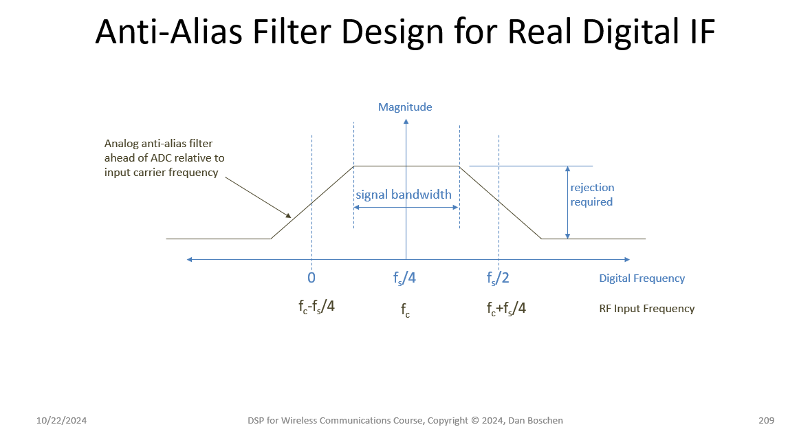
The target of $f_s/4$ is to center the signal within the first Nyquist zone which affects the analog anti-alias filter specifically, and assumes that design is symmetrical about the carrier- otherwise the result can be shifted according to the actual response in such a way that maximizes the rejection due to aliasing. This is illustrated in the graphic below. Further advantages of using a digital IF at $f_s/4$ are detailed in DSP.SE #66988.
For applications where the digital IF will then be decimated digitally (filtered and down-sampled), then the same logic applies in the design of that digital anti-alias filter that would be applied prior to the down-sampler. For that case, the digital IF should be positioned to be reasonably close to the center of one of the down-sampled Nyquist zones: $n f_s/(4D)$ where $f_s$ is the input sampling rate and $D$ is the decimation rate, and $n$ is any odd integer from $1$ to $2D-1$. For example, if there is no further decimation, then $D=1$ and we get the $f_s/4$ solution I previously used. If decimating by 2, the $D=2$, and we get the possible choices of $n=1$ or $n=3$ and $f_s/8$ or $3f_s/8$, either of which can be aliased to the final first Nyquist zone at $f_s/8$. If the digitized signal is complex as a result of IQ down-conversion, then $n$ can be over the range of odd integers from $1$ to $4D-1$.
As a final point, under-sampling increases the jitter requirements on the sampling clock so take that into consideration as well.
-
$\begingroup$ Ok! That would correspond in my example to fs = 2 GHz (Nyquist 3) or fs = 1.11 GHz (Nyquist 5). Understanding that fs = 1.11 GHz is a stronger undersampling and will require potentially sharper anti-aliasing filter. thx! Stronger understampling means jitter errors are strongly scaled too? Edit: I also forgot that Zones 2 and 4 are also possible by selecting fs = 3.33 GHz or 1.42 GHz... $\endgroup$– AlbertCommented Oct 21 at 19:37
-
$\begingroup$ I forgot to add that another constraint could be that the selected fs divided by the bandwidth is an integer number equivalent to the decimation factor (D) after digital IF digital demodulation -> D = fs/B $\endgroup$– AlbertCommented Oct 21 at 20:26
-
1$\begingroup$ Yes jitter noise noise grows according to $20\log{10}(2\pi f_{in }\tau_{rms})$ assuming you are jitter limited. Did I answer all your questions? $\endgroup$ Commented Oct 21 at 21:24
-
$\begingroup$ Maybe the point on decimation would help, in order to select the proper ADC decimation mode (by 4, 8, 16…)…thanks a lot $\endgroup$– AlbertCommented Oct 21 at 22:17
-
$\begingroup$ @Albert See my updates. Note that if you completely understand ADC aliasing and which frequency bands would fold in and how, then you understand decimation as it is the same process, and why a digital anti-alias filter is required ahead of the down-sampler (an ADC is itself a "down-sampler"). $\endgroup$ Commented Oct 22 at 12:13

