2
$\begingroup$

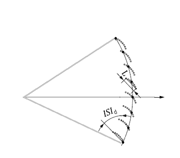
For application of syncing sampling clock phase to carrier phase of received signal where the received signal is sampled with 10 times the carrier phase and modulated with the PSK shown in the figure (Baud rate up to 0.5*fc)

enter image description here

I had many ideas to apply on my system (where interpolation is not possible) and I need your help figuring out which is the best:

  • Timing Error Delay: most proposed algorithms require interpolation
  • Hilbert filter:where generating I/Q requires shifting 2.5 samples or Fractional Delay Filter (where I need help with determining the best FIR implementation of such a filter) thanks in advance
$\endgroup$
5
  • $\begingroup$ Hi! Welcome here! $\endgroup$ Commented Apr 11, 2020 at 20:38
  • $\begingroup$ as everything in life, the answer is "it depends". There's no single best solution: you'll need to tell us what you plan on doing, what rates you're working at, what your acceptable errors are… it might be a very good start if you described the system from the top down! $\endgroup$ Commented Apr 11, 2020 at 20:39
  • $\begingroup$ well in short it's a system with carrier freq. 20MHz modulated with PSK (with phase range of 120 degree) to serve multiple baud rates where phase interval can be 8 or 4 degrees only between 2 adjacent constellations. $\endgroup$
    – user49745
    Commented Apr 12, 2020 at 6:05
  • $\begingroup$ wow, this gets more interesting and special-use-case by the minute; I honestly think that you should add a more holistic description of your modulations (including symbol rates, pulse shaping, types of PSKs used, whitening used) to your question by editing it! $\endgroup$ Commented Apr 12, 2020 at 9:57
  • $\begingroup$ updated with details :) $\endgroup$
    – user49745
    Commented Apr 12, 2020 at 22:14

1 Answer 1

1
$\begingroup$

For fractional delay filters see this article: https://www.dsprelated.com/showarticle/22.php.

Timing error delay is not used for carrier recovery. Carrier offset and symbol timing offset are not the same thing.

Carrier recovery can be done at 1 sample per symbol assuming you do timing recovery first. For this a simple phase detector is the cross product phase detector where you derive phase from the imaginary term of the complex conjugate product.

The Gardner Timing Error Detector is a good choice as it can determine timing offset over a relatively large carrier offset. If resolving timing offsets to within 1/10th of a symbol then this would be a very simple approach without further interpolation. However, I question why the OP precludes interpolation; combining a timing error detector with a polyphase interpolator is an excellent approach to resolve timing with fractional delay filters without having to increase the sampling rate- however interpolation techniques are still applied.

I have more information in other posts for both of these approaches listed below:

Gardner TED:

Isn't Gardner's algorithm and Early-Late gate the same thing?

Fractional spaced equalizer + timing (clock) recovery

Phase Detectors and Carrier Recovery Loops

Phase synchronization in BPSK

More Carrier Recovery and Timing Recovery

How to demodulation BPSK in real case(through a channel)?

$\endgroup$
4
  • $\begingroup$ couple of points about your answer: - The problem of up-sampling on my system is 10*fc is the max sampling rate of the system’s ADC, so I can’t go beyond that w.r.t interpolation - From the work Barry, Messerschnitt, and Lee: carrier recovery is a requirement for timing recovery (on a symbol level like Gardner and M-M algorithm) so here I’m puzzled about TED-polyphase filter-FDF combination. Would be great if you can share a detailed example about this combination. - I can’t decide on FDF implementations of (like windowed sinc, weighted least square method, min-max). $\endgroup$
    – user49745
    Commented Apr 12, 2020 at 22:20
  • $\begingroup$ You can interpolate without increasing the sampling rate- -this is what polyphase interpolation does. Each output of the polyphase filter is a delayed version of the signal, so you can select which one based on what delay you want. I think I have another post that details further how to implement a polyphase interpolator and use it with timing recovery---will post a link once I find it. $\endgroup$ Commented Apr 12, 2020 at 22:33
  • $\begingroup$ (In a final interpolator to the higher sampling rate you would commutate through each filter output, but you don't need to do that part, you just select the right one based on the delay needed) $\endgroup$ Commented Apr 12, 2020 at 22:35
  • $\begingroup$ @MenoNoyb Here is the link on polyphase timing recovery. dsp.stackexchange.com/questions/51285/… Also with the Gardner you do NOT need to do carrier recover first - with the Gardner Loop you can establish timing with carrier offsets as high as 1/4 your symbol rate! I was also thinking that a polyphase filter bank could also serve as your demodulator but that would involve 16 FIR filters with perhaps 4 taps each- where you sum each output over a symbol duration and choose the largest - would that approach be of interest resource wise? $\endgroup$ Commented Apr 22, 2020 at 14:03

Your Answer

By clicking “Post Your Answer”, you agree to our terms of service and acknowledge you have read our privacy policy.

Not the answer you're looking for? Browse other questions tagged or ask your own question.