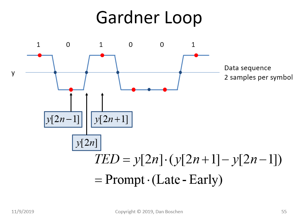
The Gardner Timing Error Detector is diagrammed in the graphic below, where two samples per symbol are used, and the error is determined using Prompt*(Late-Early), and when synchronized the center sample (Prompt) will be midway between two symbols. In contrast, an Early-Late approach uses (Late-Early), typically on a correlated symbol response, and when synchronized the Prompt sample which is between Early and Late will be centered on the correlation peak.

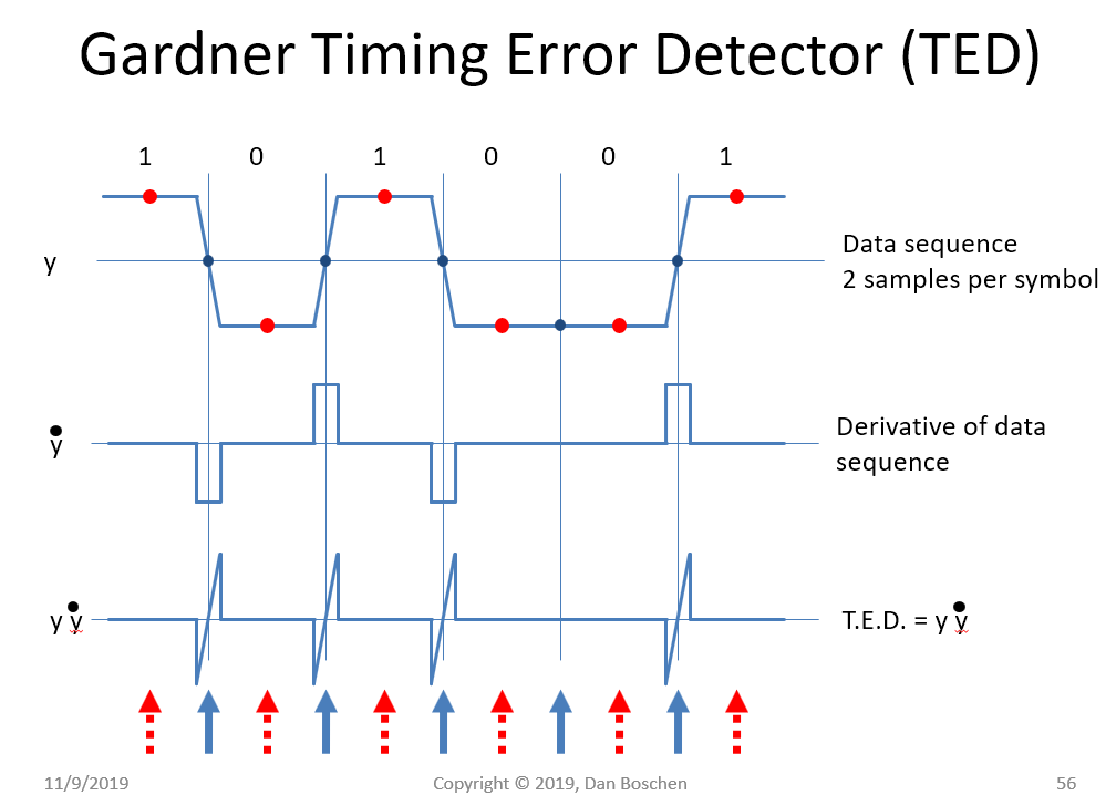
Note that the Gardner Timing Error Detector forms a Timing Error Discriminator by approximating the derivative of the waveform at the assumed zero crossing and weighing that by the actual sample value at the crossing location. (The difference equation $y[2n+1]-y[2n-1]$ is an approximation of the derivative).
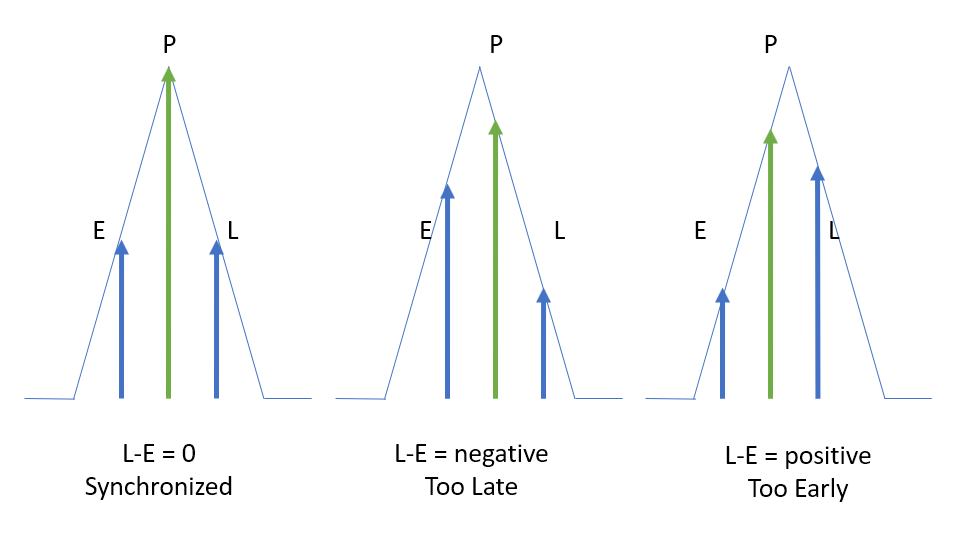
In contrast, a Early-Late gate approach approximates the derivative at the peak correlation of the data symbol. When timing is synchronized in a Early-Late gate approach, the two Early and Late samples will be a fraction of the data symbol on each side of the peak correlation. They could be spaced 1/2 a symbol, making the spacing the same as the Gardner, but the key distinguishing feature is the lock point of the center sample.
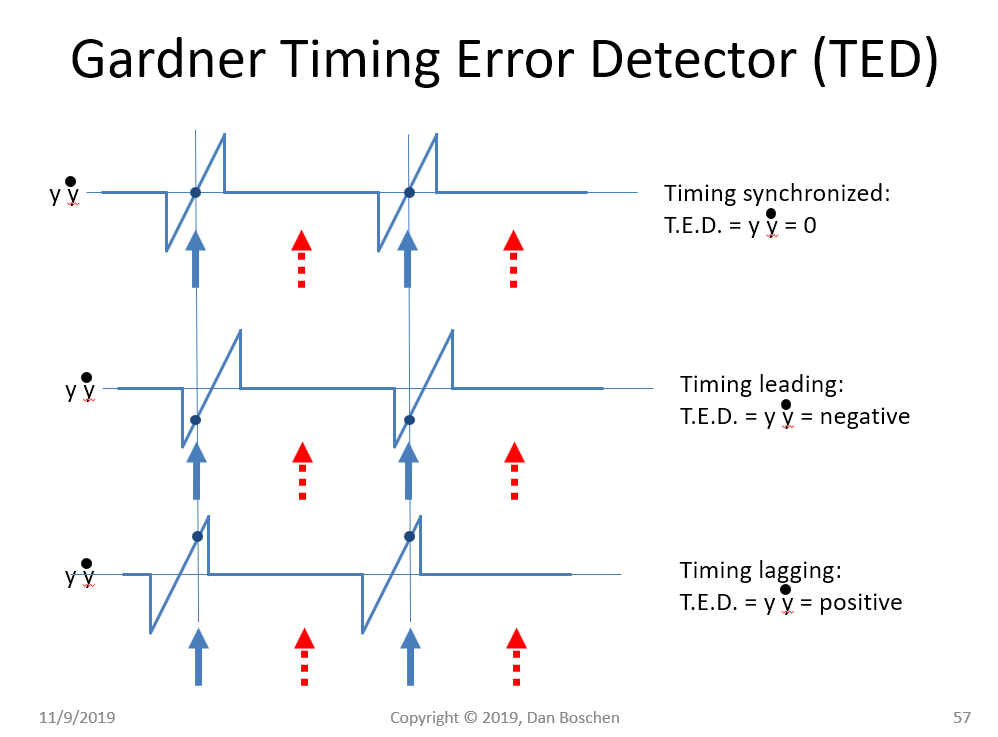
The functional operation of the Gardner as forming a discriminator by multiplying the waveform with its derivative is demonstrated by the two graphics below.


The functional operation of an Early-Late approach is shown below for the case of timing being synchronized, too late and too early. A GPS receiver is a good example where this approach is often used, where the output of the correlator of the received sequence with the GPS acquisition code used for every symbol would have the triangular response shown below, which specifically is the magnitude of the correlator versus timing offset with the code. Three correlators would be used, with the Early and Late correlator spaced approximately one half of the correlation width as shown in the diagram. The Early and Late correlators would be used to keep the Prompt correlator centered on the peak, which would be used as the recovered symbol.

Notice the key difference between the two approaches. In the Garder Loop the derivative is fairly constant in vicinity of the lock point, and it is the waveform itself providing the discrimination curve (change of error magnitude versus change in timing offset) - while in contrast with the Early-Late approach it is the derivative itself that provides the discrimination curve.


