0
$\begingroup$

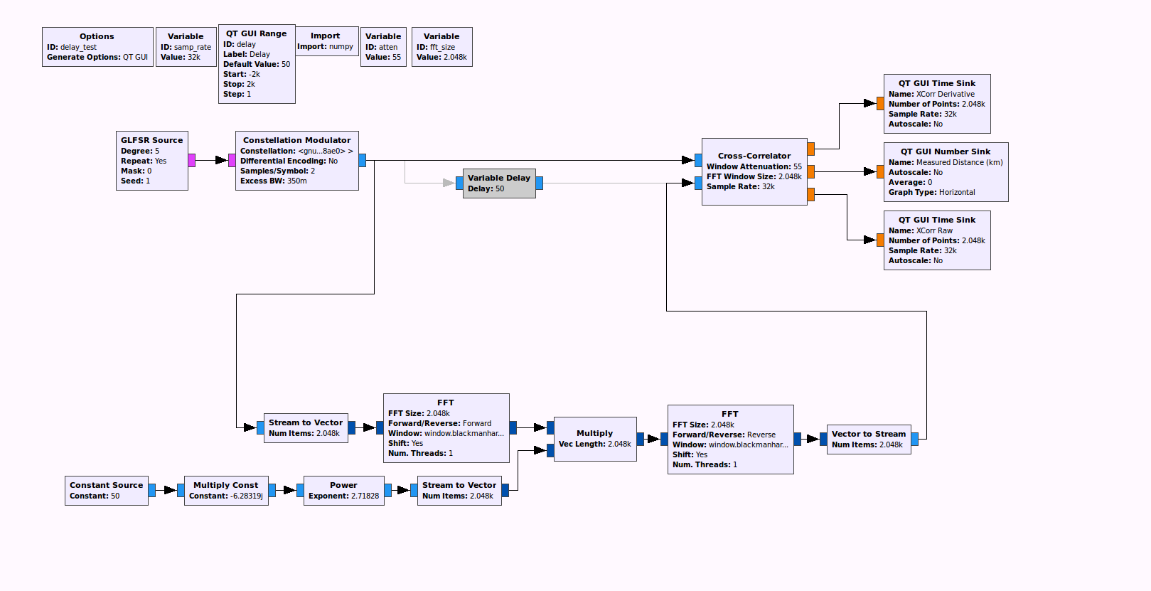
I am trying to emulate a satellite link where the delay time between the satellite and ground station changes over time due to the satellite's motion. I plan do this by converting to the frequency domain via FFT, multiplying it by $e^{-2\pi \omega_{delay} }$, and converting back to the time domain via IFFT.

However, when I implement this in GNURadio, it fails to work as I expect.

enter image description here

I generate a signal, pass it through the delay, and then match filter the original signal with the delayed signal. I then change the delay with a GUI slider. When I use the frequency-domain-phase-shifting method that I implemented, the correlation peak does not move when I change the delay. However, if I substitute in gr-baz's variable delay block, the peak does move when I change the delay.

Why does my implementation of the shifting method not work? Is it because my delay block only works with a finite window of the signal?

$\endgroup$
4
  • 2
    $\begingroup$ At first glance you are properly implementing a delay in the frequency domain, however how do you handle the stream from one FFT block to another (or are your FFT the entire message in one block?). If mutliple blocks, how do you ensure the delay implemented is contiguous? $\endgroup$ Commented Aug 16, 2018 at 20:02
  • $\begingroup$ I am not totally sure what you mean. All the FFTs in my flowchart process 2048 samples at a time. I need to be able to handle an indefinitely long signal source in real time, so I cannot load the entire signal into the FFT. Is it not possible to implement the phase shifting method with a FIR? $\endgroup$
    – rytse
    Commented Aug 16, 2018 at 20:17
  • 2
    $\begingroup$ You can absolutely implement a variable delay with an FIR filter (although that wasn't your question; your question was why the FFT approach was not working). To implement a variable delay consider a polyphase implementation (I think I have a post showing how that can be used nicely as a variable delay, will look up later if I can find it) or a Farrow Structure FIR filter. $\endgroup$ Commented Aug 16, 2018 at 20:31
  • $\begingroup$ This link may help: dsp.stackexchange.com/questions/28252/… and mathworks.com/help/dsp/examples/… $\endgroup$ Commented Aug 16, 2018 at 20:33

1 Answer 1

0
$\begingroup$

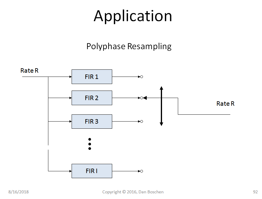
Please see the answer to this question How to implement Polyphase filter? on how to implement a polyphase interpolator, and then note that the same structure without actually commutating the output can be used as a discrete variable delay; each output is the input within the passband of the filter at a different delay in uniform discrete steps. By stepping through the output continuously as we do in the interpolator, we achieve a higher sampled version of the input. By staying at one output we get the input at a specific delay based on that filter, by changing to another output we get another delay. The design of the filter as given in the link will properly create the filters such that each is a different delay of the other (with the same ampltitude response) in uniform steps.

polyphase resampler

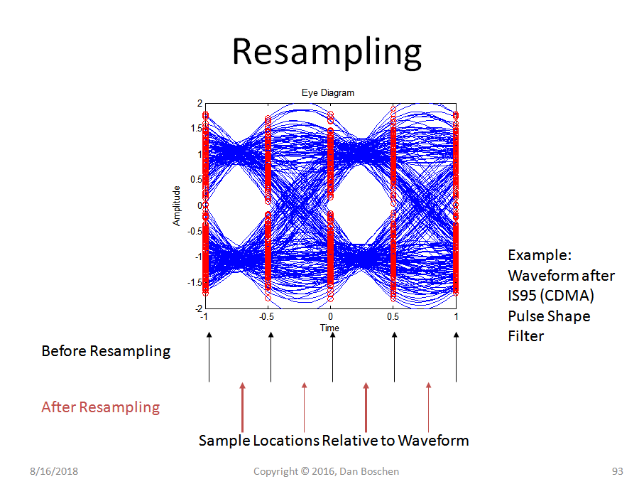
Continuing with the example shown of "Resampling" further shows how a variable delay device results:

Here is shown a IS95 CDMA waveform with 2 samples per symbol (as indicated by the red dots on this eye diagram). The analog waveform that is represented by these samples is shown in blue.

CDMA before resampling

If we used the polyphase structure as an interpolator, we would get all the samples in between the 2 samples per symbol we have, evenly spaced, given by the number of filter banks in the polyphase structure.

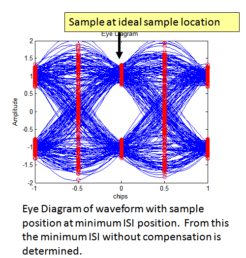
Therefore it should be clear that we can select any filter output that is closest to the desired delay we want to achieve (in this case within one symbol duration).

CDMA after resampling

As mentioned in the comments a Farrow Filter is another approach to implementing a variable fractional delay in an FIR filter.

$\endgroup$
2
  • $\begingroup$ Hi Dan, how would the output of a TED (let's say Gardner) be used to perform the resampling? Would a larger error result in a larger shift by the commutator, and if so, how is this mapping from error output to shift performed? Thanks! $\endgroup$
    – austin
    Commented Jan 6, 2022 at 6:50
  • 1
    $\begingroup$ Hi @austin - I believe you are the Austin that took all 3 of my courses last year? If so I'll email you with the reminder of where this was discussed (this was covered in DSP for Software Radio that coincidentally is starting again today). $\endgroup$ Commented Jan 6, 2022 at 12:01

Your Answer

By clicking “Post Your Answer”, you agree to our terms of service and acknowledge you have read our privacy policy.

Not the answer you're looking for? Browse other questions tagged or ask your own question.