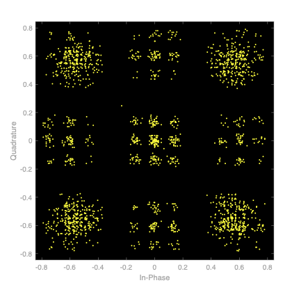
I am using a raised cosine filter in my QPSK receiver and I see this IQ diagram of the signal, but it seems off to me. Can someone explain why this happens?
This is the MATLAB code I used to generate it
% Parameters
M = 4; % QPSK
symbolRate = 1e6; % 1 megabaud
fs = 2 * symbolRate; % Sampling frequency (oversampling)
numSymbols = 1000; % Number of symbols
rolloff = 0.35; % Roll-off factor for Raised Cosine filter

% Generate random bits
dataBits = randi([0 1], numSymbols*log2(M), 1);

% QPSK Modulation
qpskModulator = comm.QPSKModulator('BitInput', true);
modulatedSignal = qpskModulator(dataBits);

% Raised Cosine Filter
txFilter = comm.RaisedCosineTransmitFilter('RolloffFactor', rolloff, ...
                                           'OutputSamplesPerSymbol', fs/symbolRate);
txSignal = txFilter(modulatedSignal);
scatterplot(txS

