Here is a simple MATLAB experiment:
alpha = 1;
R = 10;
[b,a] = butter(7,alpha*1/R);
x = resample(sign(randn(100,1)),R,1,0); % zero-order-hold
y = filter(b,a,x);
eyediagram(y, 2*R);
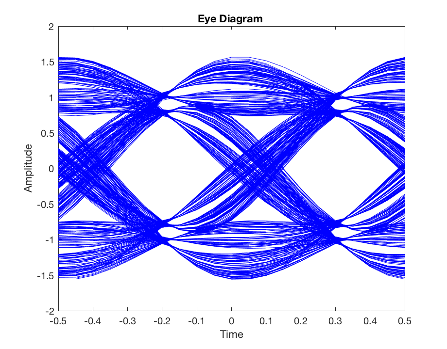
With channel twice the bandwidth than the pulses (alpha=2) the eye diagram looks clean. The first thing I am concerned that the eye diagram at the critical bandwidth (alpha=1, i.e. channel bandwidth is bitrate/2) still looks reasonably clean (little bit ISI but not too much):
I would have expected significant ISI at the critical bandwidth.
Now instead of using rectangular pulses, I use a raised cosine filter:
 hcos = rcosdesign(0, 30, R);
 x = upfirdn(sign(randn(1000,1)), hcos, R);
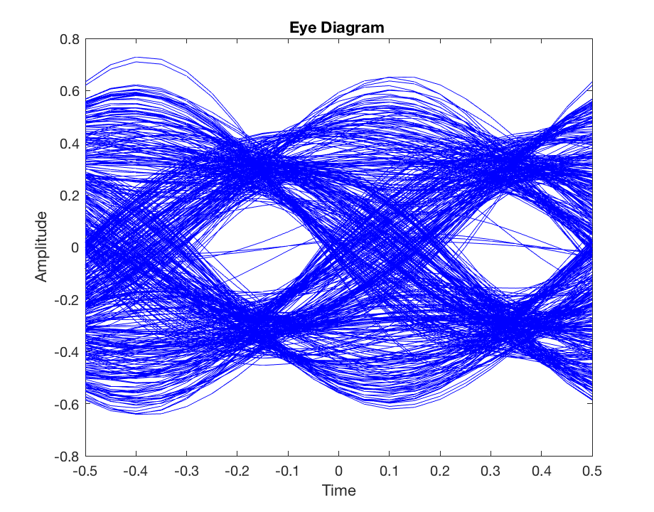
Now the eye diagram is significantly worse:
I would expect the result to be significantly better. I played with all possible rolloff factors 0...1 and number of symbols. I also tried cutting the signal at beginning/end, thinking it may be the initial transient. No changes.
What is going on here?
(Additional info: I do not want to simulate TX/RX with raised cosine but assess a channel without having to use an equalizer - in simulation. One way to do this is using an equalizer or just using a pulse shape that works close to the theoretical bandwidth - that should be raised cosine with a low beta).


rcosdesign(beta,30,R,normal). Can you also try setting the rolloff factorbetato 0.25, 0.5, and 0.75? Settingbeta=0means you're actually using a sinc pulse, which is notoriously difficult to get right since it requires a very long duration to maintain orthogonality, and this introduces numerical approximation errors. $\endgroup$