I just finished a costas loop for QPSK signal,I transmit the baseband signal and sent it into the costas loop, which worked well, but when I filter the baseband signal with root raised cosine filter during modulation, the original costas loop did not work properly. I probably know why it did not work properly, but I could not solve it.The detail are list below:
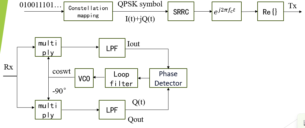 first, as the picture generate QPSK signal,carrier frequency = 2M,sample rate = 20M,symbol rate = 10k(every symbol 2000 samples),in the code I generate 32 symbols.Then symbols get through a root raised cosine filter, loaded waves, and transmit the real part.It should be noted that when SRRC doesn't exist,the expression of Tx is:
$Tx = I(t)cos((w+w_d)t+theta)-Q(t)sin((w+w_d)t+theta)$
$w$ is exact angle frequence and $w_d$ is offset of frequency because of channel,$theta$ is offset of phase angle,$I(t)$ and $Q(t)$ are In-phase components and orthogonal components.
In the receiver, it is assumed that time synchronization has been completed, only carrier synchronization is considered, and the $Tx$ is passed into the costas loop,according to linker1 my phase detector is:
$\delta = Q_{out} \cdot sign(I_{out}) - I_{out} \cdot sign(Q_{out})$
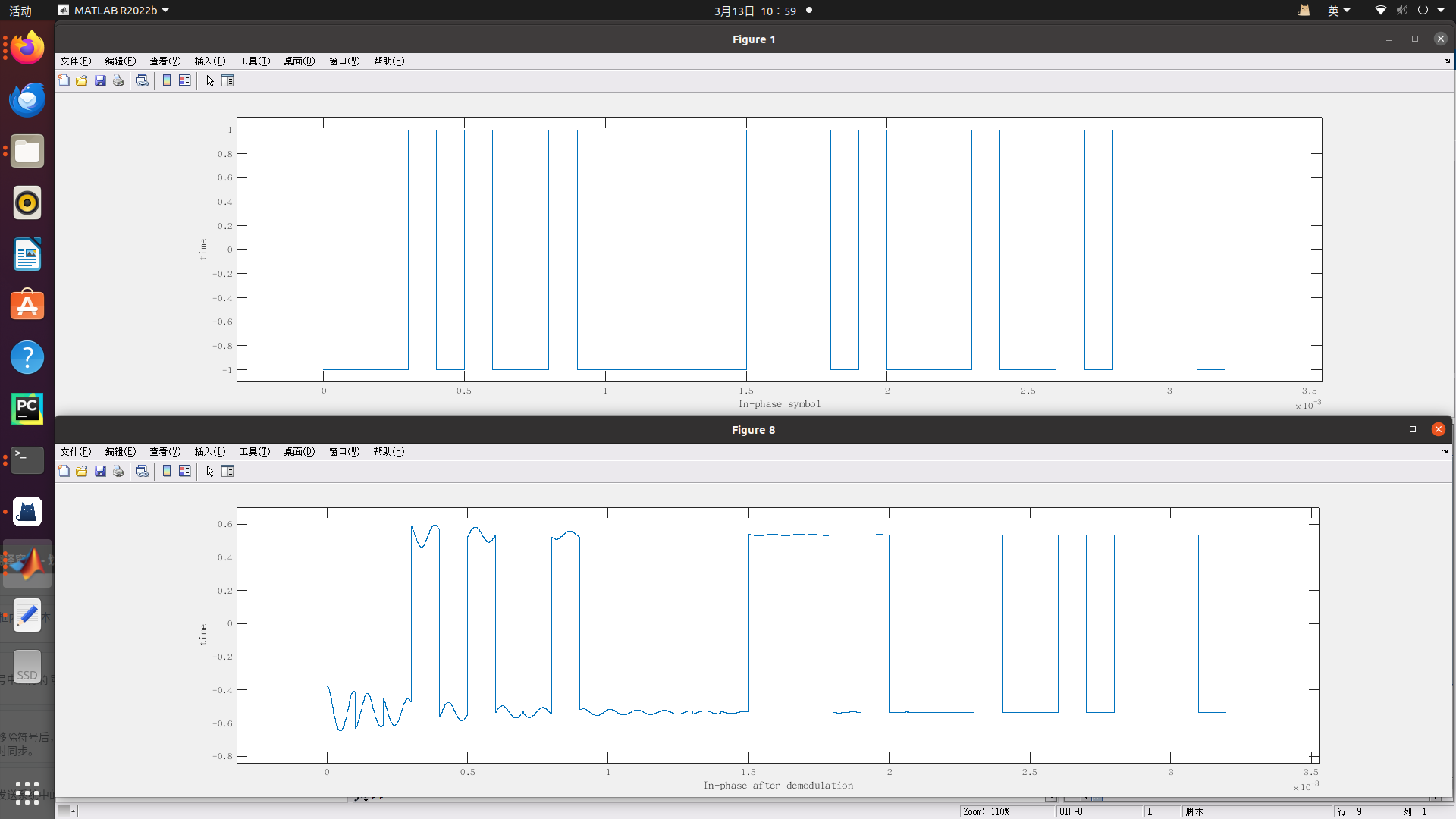
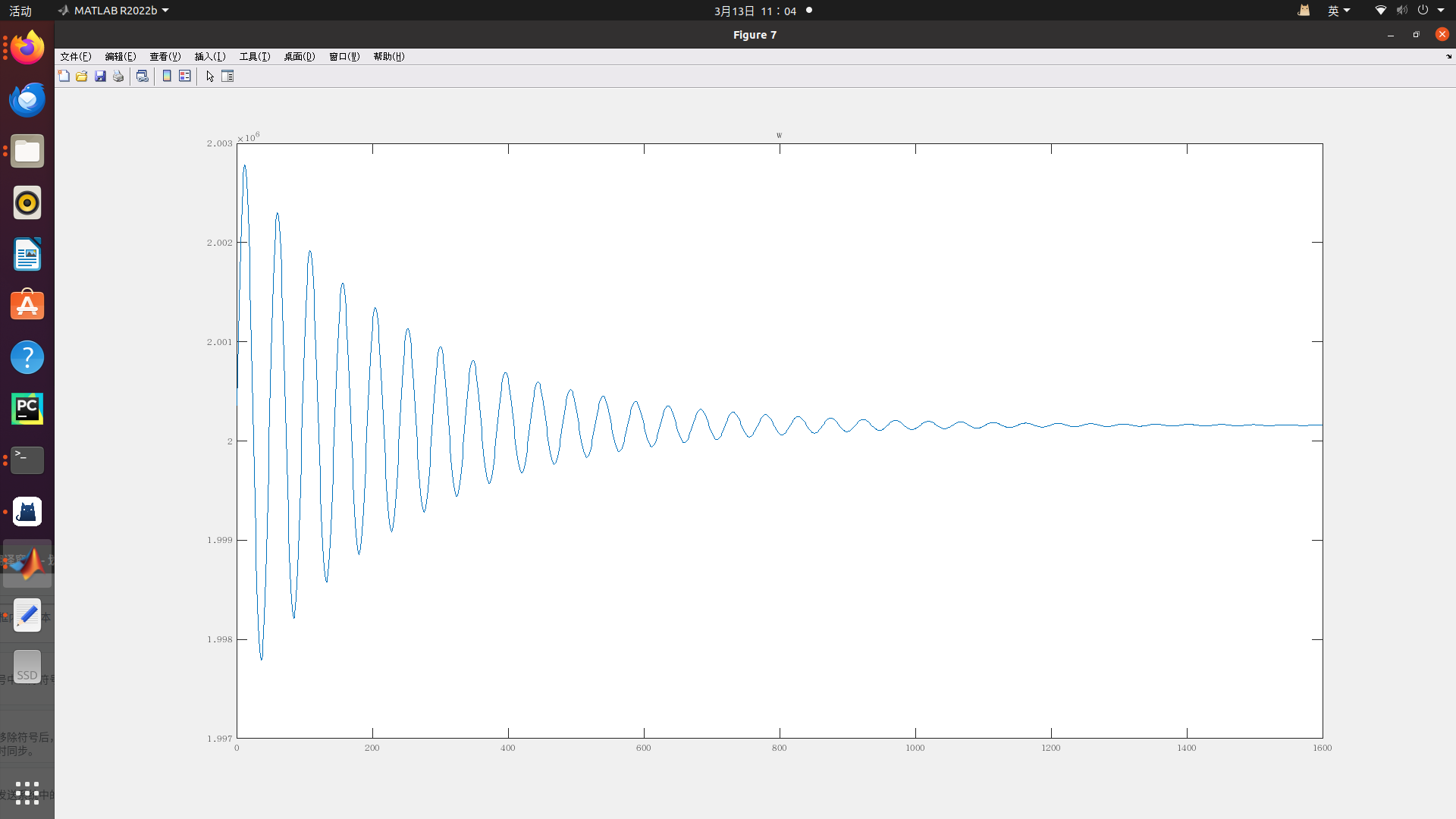
as for loop filter I use average directly instead of low-pass filter and it work well.The demodulation result and $w$ convergence result are listed follow:
But when I add root raised cosine filter(SRRC) in system, things are screwed up.Now the expression Tx is:
$Tx = I(t)*g(t)cos((w+w_d)t+theta)-Q(t)*g(t)sin((w+w_d)t+theta)$
g(t) is time domain impulse response of SRRC(Rolloff factor = 0.5,Number of symbols = 1),and now The demodulation result and $w$ convergence result are listed follow:
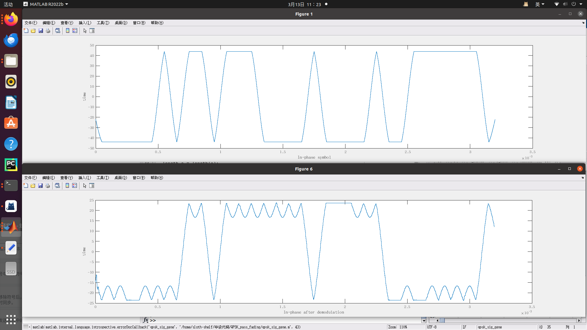
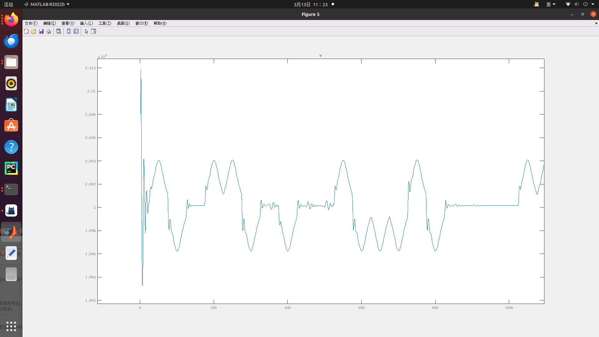 I guess this is because unlike the original rectangular pulse, the gain of SRRC at different positions in the 2000 points of a symbol is different, which leads to the same phase discriminator calculating the value sign is correct (that is, costas loop can feedback in the right direction), but the size of the specific feedback is extremely uneven. From the figure below, it can be seen that the frequency always has a big jump when it is about to lock. The above is my personal guess, and this is the problem I want to ask for help: what causes the normal phase locking after the addition of SRRC and how to solve it.
In fact,I refer to many papers and manuals, but to my surprise, almost no one thinks that SRRC has any effect on carrier-frequency synchronization, nor does it seem that the phase and frequency offset caused by SRRC are taken into account when constructing the costas loop of the system,for example this manuals QPSK receiver manual is a good reference,in page 17,the manual consider SRRC in system, however in page 21 it build costas loop normally seem SRRC have little effect on costas phase detector.This puzzled me.
My matlab code is here,I think it will help, there are 3 files, the first is how QPSK generate(if two lines of comment are added, SRRC is considered; if not, SRRC is not considered),the second is my QPSK costas loop,I pass the signal into the loop in chunks (dozens of points each, that is, dozens of sampling times to calculate a feedback amount once).And last is main function,clicking should work directly.
This is how signal generate:
% % generate QPSK signal(with carrier freq),signal format is :
% % I = Di*cos((w+wd)t+theta)-Dq*sin((w+wd)t+theta)
% % sig is qpsk transmation signal(real signal)
% % sig is input for QPSK_carrier_trace_demod_realtime.m file
function [Z,Iin,Qin,data,Di,Dq] = qpsk_sig_gene(fc,wd,theta,fs,Rb,Nsymb)
format long;
w =  2*pi*fc;
Tsym = fs/Rb;
N_sym=Nsymb;
Mmod=4;
N_bits=N_sym*log2(Mmod);
data_org = randi([0 1],1,N_bits);
data_org=reshape(data_org,[],log2(Mmod));
data_de=bi2de(data_org);
data_ds=qammod(data_de,Mmod);
re_vec=ones(Tsym,1);
data=kron(data_ds,re_vec);

Di = (real(data))';
Dq = (imag(data))';
figure
plot(0:1/fs:(length(Dq)-1)/fs,Di)
xlabel("In-phase symbol")
ylabel("time")

a = rcosdesign(0.5,1,2000,"sqrt");
Di_rcosine_tmp = conv(Di,a);
Dq_rcosine_tmp = conv(Dq,a);
length_a = length(a);
%% if want to remove SRRC,remove this segment
Di = Di_rcosine_tmp(length_a/2+1:length(Di)+length_a/2);
Dq = Dq_rcosine_tmp(length_a/2+1:length(Dq)+length_a/2);
%%
t = 0:1/fs:(length(data)-1)/fs;
Iin = Di.*cos((w+wd).*t+theta)-Dq.*sin((w+wd).*t+theta);
figure
plot(0:1/fs:(length(Dq)-1)/fs,Iin)
Qin = Di.*sin((w+wd).*t+theta)+Dq.*cos((w+wd).*t+theta);
figure
plot(0:1/fs:(length(Dq)-1)/fs,Iin)

Z = Iin +1i*Qin;
And this is how costas work:
function [I_filter,Q_filter] = qpsk_costas(Iin,fs,fc,Nsymb)
phase = 50; %initlize phase(receiver)
Kvco = 200; %feedback parameter
w = 2*pi*fc;
Tsym = 40;  %how much time(Tsym/fs)feedback once
%%
nsymb=Nsymb*50;
base = 0:1:(Tsym-1);
W=zeros(1,nsymb);U=zeros(1,nsymb);U1 = zeros(1,nsymb*Tsym);
I_filter = [];
Q_filter = [];
a = rcosdesign(0.5,1,2000,"sqrt");
length_a = length(a);
for n_trace = 1:nsymb
    t_n_trace=base;
    data_select = (n_trace - 1)*Tsym + base;
    cos_t = cos(w*t_n_trace/fs+phase); %generate cosine wave
    sin_t = sin(w*t_n_trace/fs+phase);


    Iout = Iin(1,data_select+1).*cos_t;
    Qout = Iin(1,data_select+1).*sin_t;
    Di_rcosine_tmp = conv(Iout,a);     %pass matched filter(still SRRC)
    Dq_rcosine_tmp = conv(Qout,a);

    Iout = Di_rcosine_tmp(floor(length_a/2)+1:length(Iout)+floor(length_a/2));
    Qout = Dq_rcosine_tmp(floor(length_a/2)+1:length(Iout)+floor(length_a/2));

    I_filter = [I_filter Iout];
    Q_filter = [Q_filter Qout];

    derta = sign(Qout).*Iout-sign(Iout).*Qout;   %calcu derta(error)
    u = sum(derta);
    w = w + Kvco*u;
    phase = phase + w*Tsym/fs;
    U(n_trace) = u;
    W(n_trace) = w;
    U1(1,t_n_trace+1) = derta;
end
figure
plot(U)
title('U')
figure
plot(W/2/pi)
title('w')
figure
plot(0:1/fs:(length(I_filter)-1)/fs,I_filter)
xlabel("In-phase after demodulation")
ylabel("time")
And this is main function,you can run the system by run it:
clear
fc = 2e6;  %carrier wave freqency
fs = 20e6; %sample rate
theta = 0; %initlize phase
wd = 1000; %error angular frequency
Rb = 10e3; %symbol rate
Nsymb = 32;%symbol number

[Z,Iin,Qin,data,Di,Dq] = qpsk_sig_gene(fc,wd,theta,fs,Rb,Nsymb);
[I_filter,Q_filter] = qpsk_costas(Iin,fs,fc,Nsymb);
I can't solve it, Thank you for helping.
