0
$\begingroup$

I am looking for complete OFDM transmitter chain with all the details i.e. starting from modulation symbols up to up conversion to carrier. What I have found on the web is

  1. Modulation Symbols
  2. serial to parallel conversion
  3. IFFT
  4. CP addition
  5. Digital to analog conversion
  6. up conversion to carrier

I am looking for details after CP addition. Am I missing a step between "CP addition" and "Digital to analog conversion"?

How is the "Digital to analog conversion" done for OFDM?

How do we get the final time domain signal where I can see the multiple tones with different frequency component? How do I see the modulated data on different tones?

Thanks.

$\endgroup$
6
  • 1
    $\begingroup$ This post and the other one linked in it may have a lot of the details you are looking for I believe: dsp.stackexchange.com/questions/86396/… $\endgroup$ Commented Mar 31, 2023 at 9:48
  • $\begingroup$ What I am looking for is how do we get multi-tone time domain expression when iFFT and up conversion to carrier is done. Is there any source for that detailing the equations. Thanks. $\endgroup$ Commented Mar 31, 2023 at 10:04
  • $\begingroup$ It’s a spread modulated waveform in frequency as given by the IFFT: the multiple tones in freq as represented by the FFT become the time domain signal— the same spectrum as given by the FFT can be shifted to any carrier frequency— did you review those posts as they explain that further including showing how each tone is a modulated carrier—please let me know there in a comment what still isn’t clear. $\endgroup$ Commented Mar 31, 2023 at 10:22
  • $\begingroup$ As for equations to move any baseband waveform to a carrier frequency, I can provide that here $\endgroup$ Commented Mar 31, 2023 at 10:24
  • $\begingroup$ "where I can see the multiple tones" do you mean you want to look at a scope trace and see the tones -- give up that ambition now. For arbitrary data, you'll see a scrambled-up waveform that only makes sense after you demodulate it. $\endgroup$
    – TimWescott
    Commented Mar 31, 2023 at 15:04

1 Answer 1

2
$\begingroup$

I show the details for a complete OFDM transmitter chain at this post, and this other post provides additional related details.

The OP has clarified in a comment that there is still confusion in how the upconversion to an RF carrier is done for this waveform.

The upconversion is no different than any other baseband modulated waveform where the baseband complex waveform is directly translated to either an IF (Intermediate Frequency) or RF (Radio Frequency) carrier. This process is mathematically described as:

$$x_{RF}(t) = \text{Re}\{x(t)e^{j\omega_c t}\} \tag{1}\label{1}$$

Where $x(t)$ is the complex baseband waveform typically given in real and imaginary components as $I(t)+jQ(t)$, and $\omega_c$ is the desired carrier frequency. We note that the frequency translation to a real carrier is done with a complex multiplication with $e^{j\omega_c t}$ which itself has real and imaginary components, so we can write this as $I_c+jQ_c$, and thus Equation \ref{1} becomes:

$$x_{RF}(t) = \text{Re}\{(I(t)+jQ(t))(I_c(t)+jQ_c(t))\} = I(t)I_c(t)-Q(t)Q_c(t) \tag{2}\label{2}$$

As an implementation block diagram as given in actual hardware, Equation \ref{2} becomes:
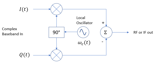
uponversion

For Direct RF the output is the RF (Radio Frequency) carrier, for a Heterodyne upconverter with an intermediate IF (intermediate Frequency), the output is the IF. As for converting from the digital samples to a continuous (analog) waveform, this conversion can take place anywhere in the block diagram shown depending on technology and design choices (cost, size, performance and power dissipation). For example, there are implementations where the baseband $I$ and $Q$ samples (for the discrete baseband waveform as $I[n]+jQ[n]$) are each converted first to analog using two D/A converters and low pass filters and then passed into the block diagram above as analog waveforms. The upconversion can then be done with RFIC's such as these. Alternatively, the processing shown in the block diagram above can all be done digitally using a Numerically Controlled Oscillator and multipliers, and then after summing the products the real signal can be converted to analog with a single D/A converter and low pass or band pass filter at either the IF carrier or RF carrier.

Below is a graphic representing the spectrum of an example OFDM waveform at baseband. In the frequency domain as shown, this is the FFT from the mapping of sub-carrier symbols to each bin, and results in a composite waveform spread across the occupied bandwidth shown. When translated to an IF or RF carrier as described above, we simply change the "0" representing DC in the graphic below to the new carrier frequency, and all other features would be the same; the processing above is simply a frequency translation.
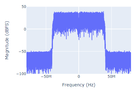
OFDM

$\endgroup$
7
  • $\begingroup$ IFFT is discrete. So how do you get x(t) from output of IFFT? $\endgroup$ Commented Mar 31, 2023 at 11:03
  • $\begingroup$ The IFFT output is complex and is the $I[n]+jQ[n]$ I described. You can either convert each to analog $I(t)+JQ(t)$ using two D/A converters, OR you can use an NCO and two digital multipliers and sum to create a single real output at a Digital IF frequency and then with that use a single D/A converter. (Or if your sampling rate is high enough and your RF carrier low enough, use a D/A converter with an output directly at RF in that case). Does that clear it up? $\endgroup$ Commented Mar 31, 2023 at 11:07
  • $\begingroup$ How does the digital to analog converter work on the iFFT? This is the detail I am looking for. $\endgroup$ Commented Mar 31, 2023 at 11:12
  • $\begingroup$ As shown in the block diagram in the linked post there is a "parallel to serial converter". Each IFFT data is a block of time data. With the P/S, each block, with the Cyclic Prefix is put one after the other to generate a stream of bits representing the time domain waveform. At this point that stream is complex, so in implementation there are two real waveforms, one for I and the other for Q. A D/A converters will take a stream of digital waveform data (x bits for each sample in time) and convert it to an analog waveform. $\endgroup$ Commented Mar 31, 2023 at 11:15
  • $\begingroup$ IFFT data is complex numbers. So I and Q are real numbers. How are these I and Q converted to stream of digital waveform data (x bits you refer to)? $\endgroup$ Commented Mar 31, 2023 at 11:22

Your Answer

By clicking “Post Your Answer”, you agree to our terms of service and acknowledge you have read our privacy policy.

Not the answer you're looking for? Browse other questions tagged or ask your own question.