4
$\begingroup$

Theory

Suppose an OFDM transmitter with four subcarriers is implemented using the structure shown below.

OFDM transmitter with four subcarriers

If the serial data input rate is 40 bps, each parallel stream will run at 10 bps. Theoretically, the spectrum (assuming BPSK modulation for each subcarrier) of the IFFT output $x$ should look like shown below (the subcarrier carrier frequencies were chosen arbitrarily).
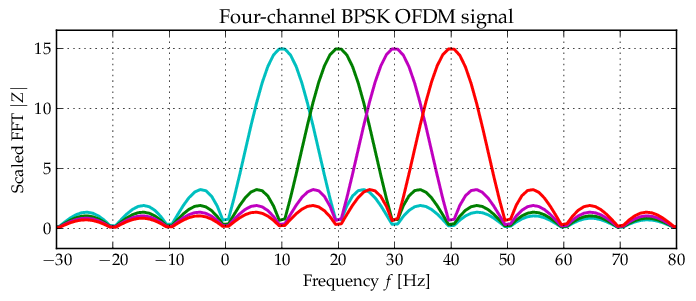
Theoretical BPSK OFDM spectrum

Each channel occupies a bandwidth from -10 Hz to +10 Hz around the subcarrier, resulting in a total OFDM null-to-null bandwidth of 50 Hz, as shown in the spectrum above.

Simulation results

However, the simulated spectrum of the IFFT output $x$ is shown below. Each input bit is represented by one sample (there is no reason to use more samples before the DAC).
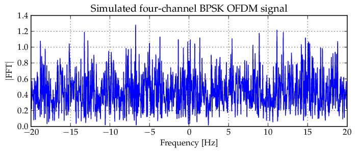
Simulated BPSK OFDM spectrum One difference between the theoretical and simulated spectra is the difference in bandwidth. The theoretical spectrum has a bandwidth of 50 Hz, whereas the simulated spectrum has a bandwidth of 40 Hz. This can be explained by setting all IFFT inputs to zero, except one, and calculating the resulting spectrum. This process can then be repeated for each of the parallel inputs numbered 0 to 3 in the transmitter structure above. The four spectra are shown below.
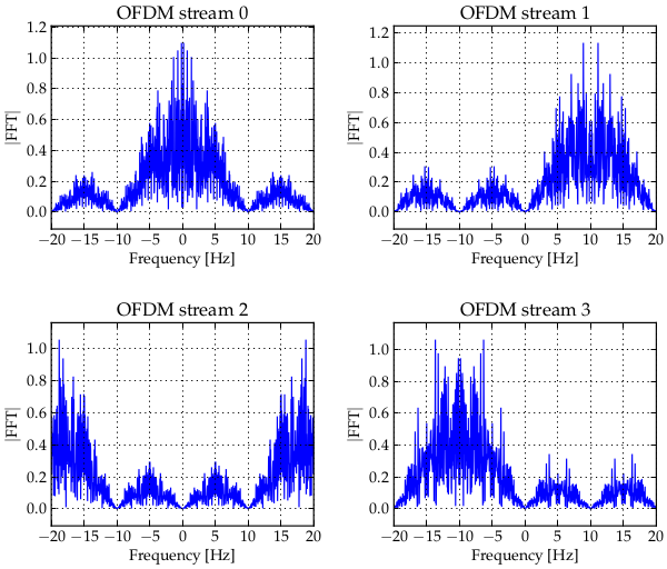
Spectra of the four parallel BPSK streams

Clearly, each parallel stream contributes a bandwidth of 20 Hz, spaced at 10 Hz. This corresponds to the theoretical BPSK OFDM spectrum, except that stream 2 is located at 20 Hz which mirrors back to -20 Hz, with the result that the total bandwidth is 40 Hz and not 50 Hz.

DAC output

In order to transmit the OFDM signal on a carrier, more samples are required per IFFT output value. The DAC should therefore employ a sample-and-hold strategy, of which the simplest is probably just repeating every IFFT output value $K$ times. The spectrum of the sample-and-hold signal $x_r$ with $K=8$ is shown below.
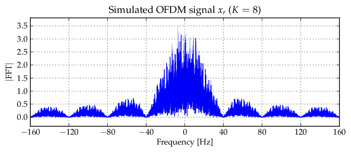
DAC output with $K=8$

The bandwidth has now increased to 80 Hz, which can again be explained by looking at the individual contributions of each of the parallel streams, shown below.
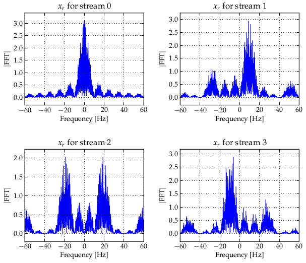
DAC output for each stream

The spectrum between -20 Hz and 20 Hz in each of the subfigures above corresponds to each respective stream shown in the OFDM streams (before resampling) figure. The harmonics caused by resampling however cause the bandwidth to increase from 40 to 80 Hz.

Question

What should the bandwidth of the BPSK OFDM signal be after resampling? Is it 50 Hz (according to theoretical graph shown), 40 Hz (simulated before resampling) or 80 Hz?

  • Should a filter be used to achieve the correct bandwidth?

  • How is OFDM typically implemented to ensure the correct bandwidth; should some subcarriers be set to zero? Should another DAC approach be used?

$\endgroup$
1
  • $\begingroup$ resampling means downsampling/ up sampling. if it is downsampling by a factor of two, bandwidth increases twofold. $\endgroup$
    – phanitej
    Commented Jan 21, 2015 at 13:56

2 Answers 2

3
$\begingroup$

What should the bandwidth of the BPSK OFDM signal be after resampling? Is it 50 Hz (according to theoretical graph shown), 40 Hz (simulated before resampling) or 80 Hz?

What you call resampling is actually modelling D/A conversion with a discrete simulation system. Resampling consists of a repetition of every sample plus low pass filtering. Your D/A converter model makes sense but it should not be confused with resampling. The D/A converter can be described by convoluting the discrete time signal with some impulse response $g(t)$. In frequency domain this corresponds to a multiplication of $X(f)$ with $G(f)$ (where these are the Fourier transforms of $x(t), g(t)$). You chose $g(t)$ to be rectangular, so $G(f)$ is a sinc function. As $x$ is a discrete-time signal its frequency spectrum is infinite and so is $G(f)$. The first spectral nulls of $G(f)$ are at $-f_\mathrm{s}$ and $f_\mathrm{s}$. So from your plot it can be seen that a sampling frequency of 40 Hz has been assumed. The useful OFDM signal is in $[-f_\mathrm{s}/2,f_\mathrm{s}/2]$.

So to answer your question: after D/A conversion the spectrum of the OFDM signal is non-zero for arbitrarily high frequencies. To find the 3-dB bandwidth $B$ you have to find the frequency $f_0$ for which $G(f_0)=0.5$, then $B=2f_0$.

Should a filter be used to achieve the correct bandwidth?

Yes, after D/A conversion, a lowpass filter with cut-off frequency $f_\mathrm{s}/2$ should be used to attenuate the spectral aliases that are caused by the D/A conversion. This so-called reconstruction filter is generally required after D/A conversion and is not OFDM specific. In cases where signal bandwidth doesn't play a role it can be omitted.

How is OFDM typically implemented to ensure the correct bandwidth; should some subcarriers be set to zero? Should another DAC approach be used?

Typically a lowpass filter with cut-off frequency $f_\mathrm{c} = f_\mathrm{s}/2$ is used. Additionally, some subcarriers at high frequencies are set to zero to enable filtering at $f_\mathrm{c}$ without distorting the useful signal. This is more important at the receiver side where the bandwidth must not exceed $f_\mathrm{s}/2$ in order to avoid aliasing when sampling the received signal. An anti-aliasing lowpass filter is usually applied at the receiver to achieve that.

$\endgroup$
2
  • $\begingroup$ By setting input 2 to zero, the first null-to-null bandwidth of signal $x_r$ changes from 80 Hz (as shown) to 40 Hz (-20 Hz to +20 Hz) which can be seen from the last figure depicting the four $x_r$ streams. This will probably also ease the filter requirements. $\endgroup$
    – aslan
    Commented Jan 21, 2015 at 19:40
  • $\begingroup$ @aslan Yes, in your system, sucbarrier no. 2 seems to be the "highest" subcarrier. $\endgroup$
    – Deve
    Commented Jan 22, 2015 at 8:35
0
$\begingroup$

Remember that OFDM is a time limited system. And because of that you have infinite components in the frequency domain ideally.

If you are not using nulls in the frequency domain, then you are not using a rectangular pulse shaping. Yes, then definitely you need to use a filter. If it is baseband communication, use a low pass filter.

The upsampling factor after the IFFT decides the bandwidth. it becomes fc/(M*fs). where M is the upsampling factor, fs is the sample rate, and fc is the cutoff frequency of the low pass filter which you are using.

Cheers, phani tej

$\endgroup$

Your Answer

By clicking “Post Your Answer”, you agree to our terms of service and acknowledge you have read our privacy policy.

Not the answer you're looking for? Browse other questions tagged or ask your own question.