The NCO is a cyclical counter that can go on indefinitely but is otherwise similar to what you suggest in that you are increment n to set the output rate. It basically is a look up table of all the values in one complete cycle, and "wraps" on an overflow so that it will output continuous cycles with no discontinuity.
I think the NCO is ideal for what you are trying to do; given its simplicity, it's ability to run indefinitely keeping track of its own position in time, its quantified noise levels that you can set to what you need, it's fixed-point implementation (with no multipliers) and its ability to change the frequency of your phasor "on the fly" as you require. I think this bottom lines the difference with the alternate approach you describe, which would not be as efficient (given the multiplications required and possible implementation in floating-point without careful mapping and scaling in which case you may as well go down the NCO path).
A little more theory may help you to see all the advantages (and simplicity) of an NCO.
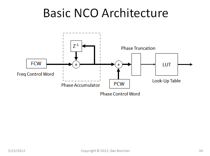
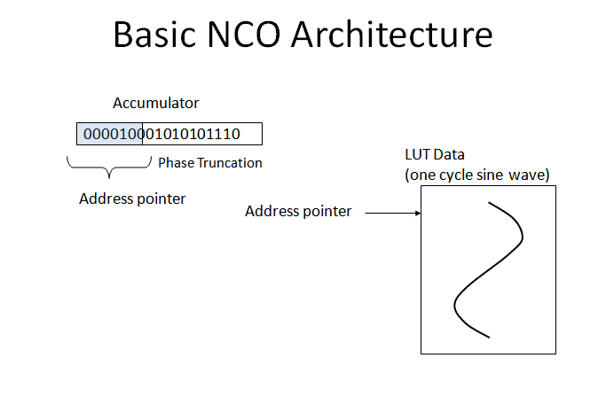
First, referring to the diagrams below for the basic NCO Architecture: A digital Frequency Control Word (FCW) sets the count rate to an extended precision accumulator (counter), optionally a Phase Control Word (PCW) for phase modulation can then be added to the output of the accumulator. The most signficant bits of this summation are then used as the address pointer to a Look-Up-Table (LUT) which holds the values for one complete cycle of a sine wave (you could also imagine having two pointers for sine and cosine to enable a complex I and Q output).
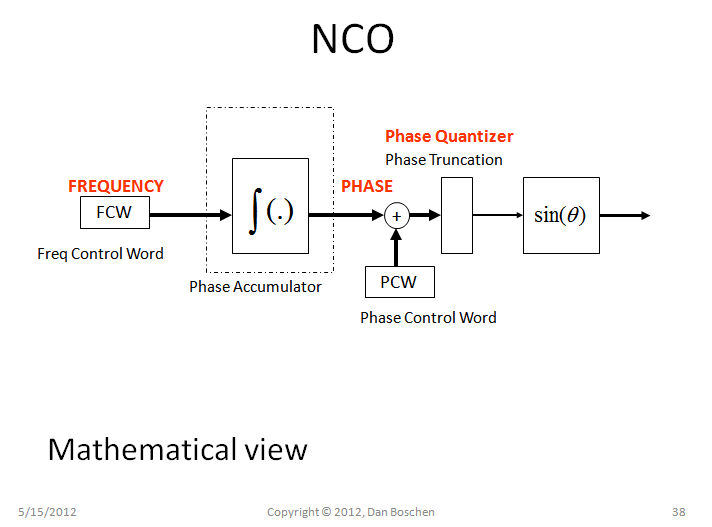
Now see the same block diagram with a mathematical view below that helps give further technical insight into the operation of the NCO. An accumulator (counter) is the digital counterpart to an integrator (if you don't see that right away, imagine sending all 1's into a counter, the output would be a ramp: 1,2,3,4,... just as you would expect an integrator output to be with a constant level at its input). The input FCW which is just a digital signal, which can change will time (as you were looking for), is a waveform that represents frequency vs time. What value of frequency for each digital word you can input I will elaborate on later, but for now know that its value at any given time is directly proportional to the output frequency. The integral of frequency is phase (and if you are less familiar with that it may be easy to see that frequency is a change in phase versus a change in time, therefore $f=d\phi/ dt$; frequency is the derivative of phase, and therefore phase is the integral of frequency.) Since our FCW input to an accumulator is the digital representation of a frequency quantity, and the accumulator is a digital integrator, then the value at the output of the accumulator represents phase versus time (which is why we can add a phase offset with PCW at this point if desired) and the accumulator counts from 0 to 2$\pi$, rolling over upon overflow.
Since the accumulator output represents phase that is changing with time, and we want to generate a sinusoid output ($sin(\theta)$), then we can simply use a LUT to perform the trigonometric function. (Note: If you have plenty of extra cycles but no memory, other techniques to calculate the sine of an angle can be done, notably the CORDIC algorithm). Beautiful right? So now how do we decide on specifics to design our NCO, and what happens when we lose all the least signficant bits in our phase word? Read on!
First, the accumulator sets the frequency resolution, and usually an extended precision accumulator is used with either 24, 32 or 48 bits typically used depending on the application. This is easy to see, imagine first FCW =1: The accumulator will step through every value, meaning the address pointer to the LUT will also step through every value in the stored sine wave, so the sine wave output will be at the slowest rate, and that rate will be as given by the "step size" in the formula below. Why step size? Because then imagine setting FCW =2, and the counter will now count by 2's and therfore go twice as fast before rolling over (and also upon rollover the counter must continue to count and that is why the NCO will continue to output the desired sine wave indefinately), put in FCW = 3 and it will count 3 times as fast etc. Therefore,
$$F_{out}= FCW\frac{f_{clock}}{2^{accum_size}}$$
So regardless of how many bits we decide to use for the LUT, the output frequency is strictly set by this formula and nothing else.

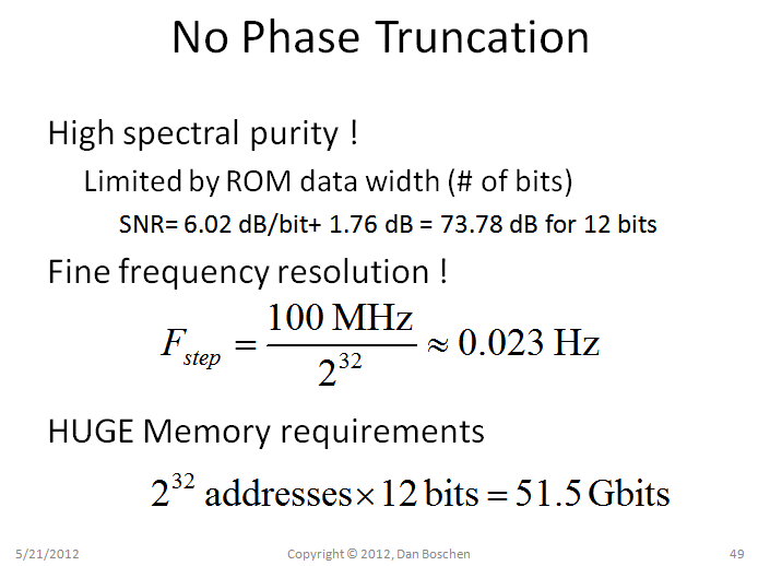
Now to briefly explain phase truncation and primary considerations: Phase truncation is when we decide to only use the most significant bits of the accumulator output to send to the LUT, and in doing this we are truncating the phase word (rounding down). To understand the implications of this, first consider the diagram below of what would happen if we did not have any phase truncation (meaning a very very large look up table, or very course frequency step size if the accumulator is small). What this picture is showing is that an impossible implementation containing a perfectly sinusoidal analog source at the specific frequency shown (with no phase noise), sampled with a perfect 100 MHz clock with a perfect 12 bit A/D converter will produce the IDENTICAL results of the NCO output, using a noisy 100 MHz clock. In fact for the NCO with no phase truncation, all of the output frequencies in multiples of $f_{step}$ as provided by the formula above will be this precise, with quantization noise at the output being the only noise source (which you can control by setting the output word width). You can see if you imagine different cases that without phase truncation, the look up table will provide the exact output at any given point in time that is required (limited to the quantized frequency choices with FCW, but that step size can be very small with large accumulators). The waveform will be very smooth without any skips or hiccups, in other words, pure.

So this is great, consider the example with a 32 bit accumulator, and 12 bit output of the LUT; providing very fine frequency resolution with great spectral purity (and 6 dB better for every additional bit you add to the output width)...until you get to the memory requirements! An herein lies the motivation to consider phase truncation.
Phase Truncation
With phase truncation, memory requirements are significantly reduced at the expense of an additional noise source (phase noise). What we will see if that the noise will be well understood and can be planned to be well below any given requirements (as a trade with memory required).
Also to mention for memory optimization only a quarter cycle is needed since the remaining portions of the cycle can be derived from the first quarter cycle. There are many other memory optimizations as well such as interpolation between values (most common), and to mention without explanation, Hutchison Algorithm and Sunderland Algorithm, as well as the Cordic Rotator previously mentioned.
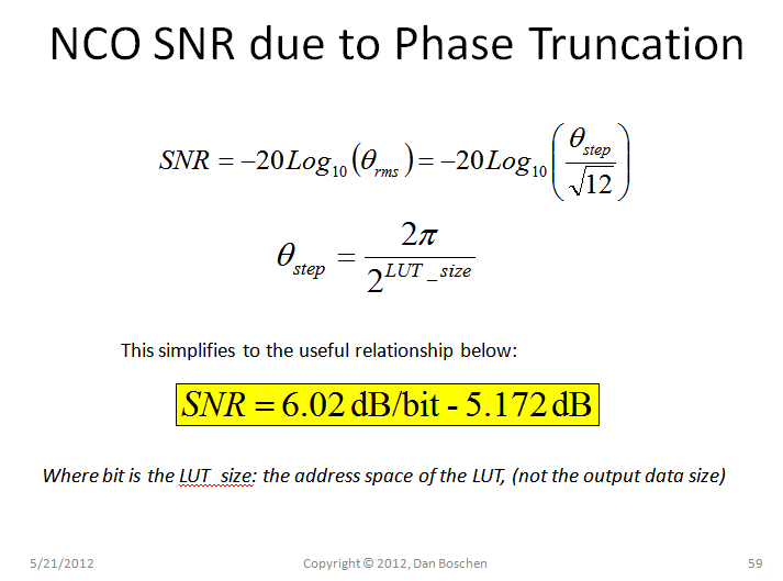
The phase noise pattern itself from phase truncation will be a sawtooth function of phase versus time, representing the truncated values that are missing. From this, the useful relationship of SNR to phase truncation is given as in the picture below. Here SNR is the power of the desired sine wave output relative to the power of all spurious output due to the phse truncation. This formula applies when the small angle criteria applies (when $sin(\theta) \approx \theta$) and comes from the rms value for a sawtooth function (or equivalently the standard deviation for a uniform distribution) which is $\frac{D}{\sqrt{12}}$ where D is the peak to peak height of the ramp or width of the distribution. This formula is combined with the quantization noise contributions from the LUT for a digitized signal (using a similar formula: 6 dB/bit + 1.76 dB also derived from our $\sqrt(12)$ factor since quantization noise can be modeled as a uniform distribution!), to address all noise sources in the NCO. To use this formula, the number of bits in the formula is the number of bits sent to the NCO (number of phase bits not truncated).
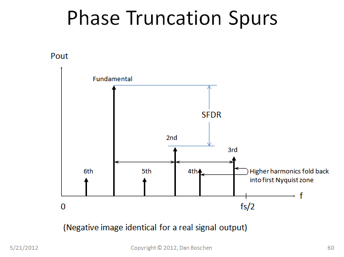
Finally we may be interested in the spurious free dynamic range (SFDR) which would be the power level of the strongest spur relative to our output signal (as opposed to the sum power of all spurs in SNR). The power of the strongest spur due to phase truncation is simply 6.02 dB/bit, where again bit is the number of bits sent to the LUT. (This can be derived by taking the Fourier Transform of the ramp pattern which represents our phase error, again applicable to small angle approximations). All the spurs are integer harmonics of the fundamental output frequency, many of which will have digitally folded in the first Nyquist zone of our implementation, as suggested in the diagram below. Unlike the diagram, the 2nd harmonic is not necessarily the strongest spur, but helps to give context to the idea of spurs and SFDR.
Dithering
Dithering is the process of adding a small amount of noise (for example, use a LFSR generator as the PCW input) which will improve the SFDR at the expense of SNR. The overall noise power increases (due to our additional additive noise), however the spurious levels can be substantially reduced in the process.


y[i] = sin(coef*t)withtbeing a 32-bit float. The absolute precision of floats decays exponentially with magnitude, sot += dtwill rapidly lead to rounding errors astbecomes large. Probably not an issue if using doubles. $\endgroup$