Say, for LTE BW 20 MHz, I have total 2048 SubCarrier at IFFT Input leading to 2048 Output (Complex) at IFFT Output, and in 1 OFDM Symbol (useful symbol length) of time 66.67 usec, the sampling rate will be determined to be 30.72 MHz. So is all this extension of 1200 Active SubCarrier by adding 848 null SubCarrier just done so that IFFT can work in full fledge or is there some tricky implementation beneath which is helping DAC or any other aspects too? Also why people refer to this 2048 as number of frequency samples, ideally samples should mean the time domain samples, please correct me if I am wrong.
1 Answer
The sampling rate of 30.72 MHz refers to a complex sampling rate of the baseband signal. For a bandwidth of 20 MHz, the single sided bandwidth would be 10 MHz and the minimum sampling rate according to Nyquist would be 20 MHz (and we would do something larger than this for practical reasons). So there is no issue here with the 30.72 MHz sampling rate reported.
In the modulated waveform, 2048 refers to a frequency sample since it is the sub-carrier as given by an FFT. The modulated sub-carriers as a composite waveform is converted to a time domain waveform for transmission using an IFFT. The received waveform is a time domain waveform, and we convert it back to modulated sub-carriers in the receiver using an FFT.
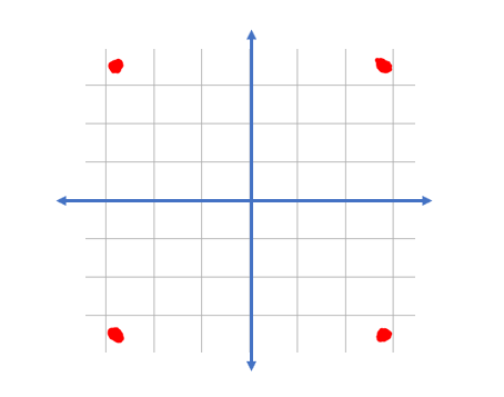
As a simplified example, consider a single carrier QPSK waveform with a constellation at any carrier given as shown in the following diagram; we see that the carrier for any particular symbol transmitted can take on a value of magnitude 1 and angle either +45°, +135°, -135° or -45°.
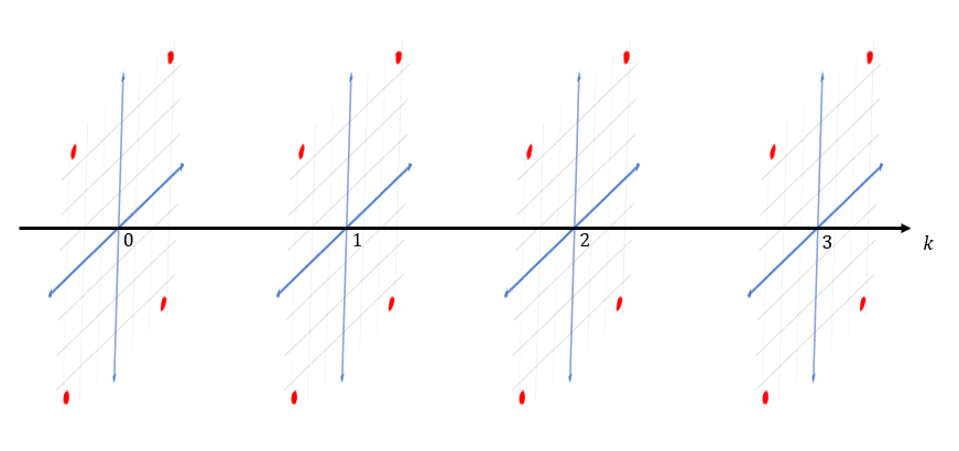
Below shows a multi-carrier example, where we use four closely spaced carrier each with an independent QPSK modulation. The horizontal axis is representing the carrier frequency, and for each carrier as in the single carrier case within a given symbol the carrier has a magnitude 1 and angle either +45°, +135°, -135° or -45°. Thus in this case with a QPSK sub-carrier , pairs of data bits are mapped to one of these four complex symbol locations. We could, in fact, implement this as four separate QPSK modulators and combine the signals together at RF and pass through a single antenna.
We can now see that the above can also be represented, as a single block in time corresponding to one symbol duration, as a 4 point DFT where each bin has a magnitude of 1 and, according to the data mapped, one of the 4 possible phase values. Hence for OFDM we can map data to these possible symbol locations in an FFT directly, and then to produce the equivalent time domain waveform we take the IFFT result of this to generate the waveform that we can then upconvert to the actual higher frequency RF carrier used for transmission.
We see this in the block diagram for the transmitter using OFDM, where the data itself represents frequency once mapped to complex sub-carriers and converted to time using an IFFT (beyond the scope of this answer but an addition item we need to be aware of is the cyclic prefix to give us protection against delay spread in the channel, which is added in the transmitter and removed in the receiver):
Also related to this question and the objective / purpose of the null subcarriers, see this other existing post:
-
$\begingroup$ Sorry for my ignorance but which part of your answer answers the question "is all this extension of 1200 Active SubCarrier by adding 848 null SubCarrier just done so that IFFT can work in full fledge or is there some tricky implementation beneath which is helping DAC or any other aspects too?"? Thanks. $\endgroup$ Commented Jan 9, 2022 at 11:25
-
$\begingroup$ I mean of course no problem of 30.72MHz rate sampling a 20MHz signal, but why do we need 30.72MHz instead of a smaller rate, e.g. 15.36MHz to grap the 1200*15kHz=14.4MHz useful bandwidth? $\endgroup$ Commented Jan 9, 2022 at 11:30
-
$\begingroup$ @CathMaillon The tighter the sampling rate is to the passband, the more complicated all prior filtering is both in analog and digital domains. Having a wider transition band allows for simpler filtering. This post may interest you: dsp.stackexchange.com/questions/61391/… $\endgroup$ Commented Jan 9, 2022 at 12:06
-
$\begingroup$ Thanks for the link. So all of this doubling the sampling rate from 15.36MHz to 30.72MHz is for facilitating filtering? It seems too much ... $\endgroup$ Commented Jan 9, 2022 at 18:28
-
$\begingroup$ For a 20 MHz LTE channel the occupied bandwidth is 18 MHz (I believe) so 15.36 MHz is insufficient. This may help you: rfmw.em.keysight.com//wireless/helpfiles/n7624/Content/Main/… $\endgroup$ Commented Jan 9, 2022 at 18:42


