In the process of OFDM Signal generation. We take symbols (constellation symbols) and map it to a sub-carrier (real analog time domain) harmonics of 15khz, add different sub-carriers separated by 15khz gap (say SubCarrier are N), now we get our OFDM Signal and we can send it. To overcome this generation of Freq of multiple of 15khz we use the process of IFFT (fast IDFT process) and in the formula of it we see symbol treated equivalent as Freq point value multiplied with exponential component--> we say this represents carrier which opens to be cos+jsin, but my carrier was never complex it was real where I wanted to send data. Does it means my output of IFFT which is discrete time signal is complex and then I convert it to analog and upconvert it-->this is still complex signal? So initially we were mapping complex symbols on real, adding them and sending. Now we are mapping complex symbols to complex waves and sending?
3 Answers
When you map data to subcarrier symbols in OFDM, that IS a complex mapping. Each "constellation symbol" becomes the magnitude and phase for an FFT bin, so ultimately when you take the Inverse FFT, you are creating the time domain waveform that would represent all of those constellations being broadcast in parallel on closely spaced carriers each separated in frequency by $1/T$ where $T$ is the symbol update rate.
For the simplest case, consider QPSK modulation for each subcarrier: for that you could map pairs of data bits onto each subcarrier according to:
11: $exp(j \pi/4)$ or equivalently $0.707 + j0.707$,
10: $exp(j 3\pi/4)$ or equivalently $-0.707 + j0.707$,
11: $exp(-j 3\pi/4)$ or equivalently $-0.707 -j0.707$,
01: $exp(-j \pi/4)$ or equivalently $0.707 -j0.707$
The OFDM signal as the FFT, and its time domain signal as the IFFT are both complex signals at baseband when mapped according to the example above (and must be complex in order to represent each possible point in the constellation which itself is complex). We can then translate a complex baseband signal (which requires in implementation two real data paths: one for "I" or in-phase component and one for "Q" or quadrature component) to a real IF or RF carrier frequency using an quadrature up-conversion (two multipliers or mixers, a sine and cosine local oscillator and combine the output).
If you understand single-carrier modulation (such as the QPSK example here), then consider OFDM as the most efficient way to send multiple low-rate QPSK or QAM modulations in parallel on closely spaced carrier frequencies. That is what the FFT is (closely spaced frequencies each with their own magnitude and phase, as a complex number), which makes it convenient for OFDM implementation.
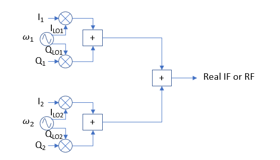
Below is a further attempt to add some clarity starting with the OP's perspective of a QPSK or QAM modulator. The first drawing below shows how we could implement an OFDM transmitter the "hard way" by grouping together traditional QPSK/QAM modulators with closely spaced carriers given by $\omega_1$ and $\omega_2$. I show two such groupings but you can extend it to $N$ modulators, with carrier frequencies spaced by the inverse of the symbol rate or $1/T$:
In the initial implementation shown above, $I_{LO1}$ and $Q_{LO1}$ represent the higher frequency carrier frequencies (either an IF or RF carrier) as $\cos(\omega_1 t)$ and $\sin(\omega_1 t)$ respectively, and similarly for $I_{LO2}$ and $Q_{LO2}$ for carrier frequency $\omega_2$. $I_1$ and $Q_1$ represent the real and imaginary portions of the selected symbol for the upper modulator, and $I_2$ and $Q_2$ represent the complex symbol for the lower modulator (given by the mappings first introduced, for example). Thus the data input pair $I_1$ and $Q_1$ represent a complex data path given as $I_1+jQ_1$ and similarly the local oscillator is a complex data path given as $I_{LO1}+jQ_{LO1}$ for the upper modulator, and similarly for the lower modulator. Thus it may appear that the two multipliers form a complex multiplier, and they are indeed part of that. Assuming in this case we are doing the frequency translation with a high enough carrier frequency, we can immediately take the real part of the output without interference from the complex conjugate spectrum any real waveform will have. Note below the equivalent complex representation that one of the two modulators shown above would be given by the complex multiplication:
$$Re\{e^{j\phi_1}e^{-j\omega_1 t}\}$$
$$=Re\{(I_1+jQ_1)(I_{LO1}-jQ_{LO1})\}$$ $$= I_1 I_{LO1} + Q_1 Q_{LO1}$$
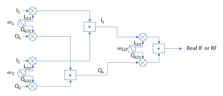
Given this, consider what we would need to do if $\omega_1$ and $\omega_2$ were at "baseband", for instance at $\omega_1 = -2\pi 1/T$ and $\omega_2 = 2\pi 1/T$. We would need to represent these with complex signals (I and Q) until we can translate this to a higher IF or RF frequency using an "IQ Mixer" (to refer to an analog implementation) since given $\omega_1 = -$\omega_2$, they cannot be independent data symbols with a real waveform that must be complex conjugate symmetric (but can be with a complex waveform!). Such an implementation the "hard way" is given by the diagram below:
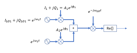
And similarly in more compact form with the wide data paths representing complex waveforms (where each wide trace below is a complex data path as $I+jQ$):
Above as mentioned is the "hard way" to implement multi-carrier with orthogonal spacing (spacing the carriers by $1/T$ with $T$ being the symbol rate provides orthogonality), where the drawing above can be extended out to $N$ carriers.
OFDM allows us to do this the "easy way"! Notice that each carrier is simply a bin in the FFT (if we were to take an FFT of the combined result). So with OFDM we simply start with that, load the constellation onto each bin according to our mapping and then take the inverse FFT to create the equivalent analog signal that the above would create (as a complex signal that we would need to translate to a real RF carrier at an IF or RF frequency). There is a lot more detail with OFDM such as adding a cyclic prefixes to avoid the effects of delay spread that I am not mentioning here, but the intention with this introduction is to remove the mystery of how the complex signals for each DFT bin can represent the equivalent analog waveform to a multi-carrier QPSK/QAM system. Further the above shows the most generic form fully utilizing the independent bins in a full FFT, but OFDM implementations can also be done with Hermitian symmetry ($N/2+k = k^*$) such that the direct output can be real such that and IQ frequency translation is not required.
The complete OFDM transmitter as is shown below in its typical form, where we see this is an equivalent structure to what was developed above and the importance of the complex values for each QPSK/QAM symbol as represented by $k_0$, $k_1$, etc.
If the frequency translation with complex signals as depicted in this post is still not clear, the follow post may also be helpful and get to root of the OP's question that goes far beyond OFDM specifics:
In the process of OFDM Signal generation. We take symbols (constellation symbols) and map it to a sub-carrier (real analog time domain) harmonics of 15khz, add different sub-carriers separated by 15khz gap (say SubCarrier are N), now we get our OFDM Signal and we can send it.
In short: no. You can't generate an OFDM system just by placing carriers in a regular grid in analog domain. These carriers need to carry a synchronized, rectangular symbol sequence, else it's not OFDM.
A system that does that inherently is a time-discrete system with a DFT as synthesizer bank.
I never liked the explanation of OFDM as "just" an easy-to-implement analog multicarrier system. The requirements to the relationship of these carriers inherently make the system discrete-time.
but my carrier was never complex it was real where I wanted to send data.
You should be thinking of complex baseband here – the center frequency of the OFDM signal is completely irrelevant.
So, no. your carrier was not real to begin with.
Does it means my output of IFFT which is discrete time signal is complex and then I convert it to analog and upconvert it-->this is still complex signal?
You will need to understand equivalent complex baseband before you can understand OFDM! This is really not something we can explain as an "aside" in an answer, but it's at the heart of every modern communications scheme, so:
no, your passband signal is not (usually) complex.
So initially we were mapping complex symbols on real,
no, you're mapping complex symbols to complex-valued subcarriers in complex baseband,
adding them
err, you do that by doing an IDFT, and that has the addition internal,
and sending.
mix them up to a carrier frequency and then transmit that.
The 'IFFT' method of generating 'OFDM' is misleading. A set of 'N' QAM vectors (complex values) presented to an IFFT module will result in 'N' output vectors. If that set of N output vectors is considered to be a complex-valued time-domain sequence, and if it is transmitted using quadrature modulation, then that block sequence would need to be transmitted repeatedly, in looped fashion (ie. periodic) in order for the spectrum to be 'OFDM'. Otherwise, if sending that particular complex N-value block sequence just once only, then that would just be quadrature modulation. Not 'OFDM'. You need to have at least 'some' physical periodicity in your IFFT sequence in order to even begin to consider the existence of sub-carriers. No periodicity, no sub-carriers, and no OFDM symbols, as we need periodicity in the time domain to make that 'connection' with the counterpart frequency domain 'vector components'. This also means that the IFFT signal that everyone is talking about is not actually an OFDM signal at all. It is just quadrature modulation. That's because each IFFT chunk or block that is sent out is not periodic. You need to physically create periodicity in the time-domain before we even begin to contemplate existence of sub-carriers and/or carriers that represent the vector components in the frequency domain.


