7
$\begingroup$

This is a "DSP Puzzle", Please preface your answer with spoiler notation by typing the following two characters first ">!" as the intention is for readers to think through what the solution might be first (the ones that want to participate, others can hover over immediately to see the solution).

A second order "type 2" Phase Lock Loop is required in order to track a phase ramp with time with zero error. A phase ramp is a frequency step. Similarly a third order "type 3" PLL would be required to track a frequency ramp (phase acceleration), which I have summarized in the graphic below. The "Type" refers to the number of poles in the open loop transfer function at the $s=0$ in continuous time or $z=1$ in discrete time loops, since these represent pure integrators. An integrator has infinite gain at DC and hence infinite suppression of DC error.

A second order type 2 PLL is often implemented with a proportional-integral loop filter, adding the second pole in addition to the oscillator which has an inherent pole since it integrates phase (controlling the output frequency of the oscillator directly is controlling the integral of the phase of the output).

The question is: There is a way to implement a similar tracking system to track a phase ramp with zero error using two first order PLL's. How do we do this?

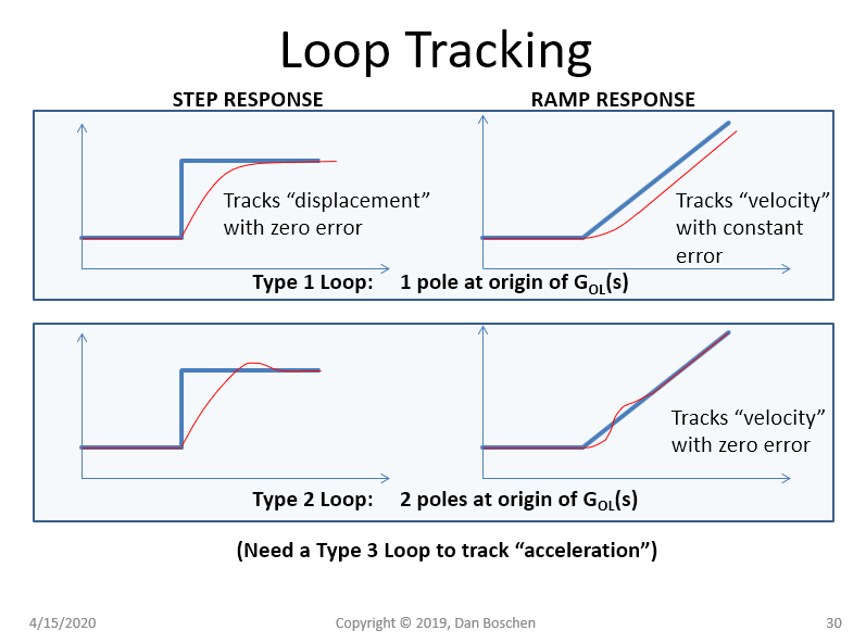
Loop Tracking

$\endgroup$
4
  • 1
    $\begingroup$ In case somebody doesn't know how to do the spoilers: meta.stackexchange.com/questions/285026/… $\endgroup$
    – Engineer
    Commented Apr 15, 2020 at 15:14
  • 1
    $\begingroup$ Thanks finally figured it out. Painful--need to add <br> or <br><br> instead of returns for line breaks. The spoiler ends as soon as you enter return. (I think I was looking at the same post!) $\endgroup$ Commented Apr 15, 2020 at 15:18
  • $\begingroup$ Yeah it seems like there are a couple ways but no easy way! $\endgroup$
    – Engineer
    Commented Apr 15, 2020 at 15:19
  • $\begingroup$ You think there would be some sort of \begin{spoiler} and \end{spoiler}... since it interprets HTML maybe the whole thing can be enclosed in a div and then somehow id’d as such $\endgroup$ Commented Apr 15, 2020 at 15:26

1 Answer 1

3
$\begingroup$

Notation: Incoming carrier frequency : $f_c$ and Local Oscillators synthesized frequency : $f_o$.

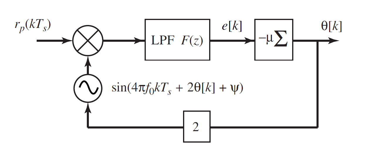
A First Order PLL to track a constant phase offset $(\phi)$ in the received carrier sinusoidal is based on the following PLL daigram. In working of the single PLL Loop it is essential that $f_c = f_o$:

PLL1 (image courtesy : Software Receiver Design by Johnson, Sethares & Klein)

Here, $r_p(kT_s) = BPF_{2f_c} \{ r(kT_s)^2 \}$, meaning received signal is squared and then bandpass filtered with BPF's center frequency at twice carrier frequency $2f_c$. This preprocessing is done to emphasize the carrier, since this will boost carrier SNR. So, input to the PLL is basically, $$r_p(kT_s) = cos(4\pi f_c k T_s + 2\phi)$$

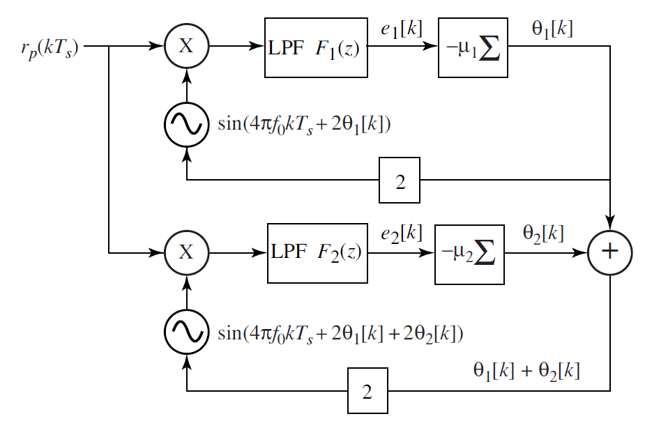
Now if instead of constant phase offset of $\phi$ if we are having a constant frequency offset of $\Delta f = f_c - f_{o}$ and a constant phase offset of $\phi$ in carrier frequency then, we can extent this single PLL Loop to a combination of 2 PLL loops as follows: PLL2(image courtesy : Software Receiver Design by Johnson, Sethares & Klein)

Here, input to this frequency Tracking PLL is as follows: $$r_p(kT_s) = cos(4\pi (f_c - \Delta f)k T_s + 2\phi)$$

Now, if the first Loop processing is worked out, it can be shown that it tracks a ramp:

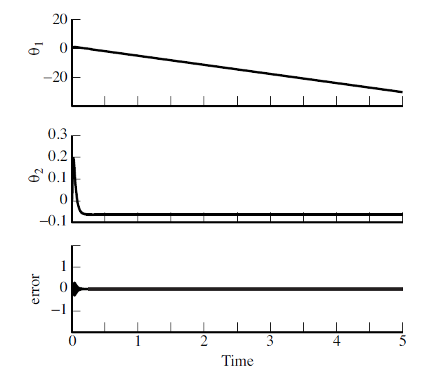
$$\theta_1[k] \rightarrow 2\pi (f_c - f_{o})k + \beta$$, where $\beta$ is the y-intercept of the ramp being tracked by first PLL.

This is added to $\theta_2[k]$, which makes it possible for the $2^{nd}$ PLL to track the frequency accurately :

$$\theta_2[k] \rightarrow \phi - \beta$$ , which mean, $$\theta_1[k] + \theta_2[k] \rightarrow 2\pi (f_c - f_{o}) + \beta + \phi -\beta$$ $$\theta_1[k] + \theta_2[k] \rightarrow 2\pi (f_c - f_{o}) + \phi$$, And this sum is being used to drive the sinusoid of Local Oscillator, hence the local oscillator is now generating a sinusoid which is synchronized with $r_p(kT_s)$ in both frequency and phase.

Basically, top PLL Loop is tracking a ramp and hence generating the correct frequency for the bottom loop, and bottom loop is further correcting the residual phase error.PLLerrorTheta(image courtesy : Software Receiver Design by Johnson, Sethares & Klein)

$\endgroup$
3
  • $\begingroup$ Please put >! in front of your paragraphs? that will put it in "spoiler notation" since this is a puzzle $\endgroup$ Commented Apr 15, 2020 at 14:29
  • $\begingroup$ @DanBoschen Done, as far as I could! :) I am new to this. $\endgroup$
    – DSP Rookie
    Commented Apr 15, 2020 at 14:37
  • $\begingroup$ Very nice $DSP Rookie, thanks for the details! $\endgroup$ Commented Apr 15, 2020 at 15:00

Your Answer

By clicking “Post Your Answer”, you agree to our terms of service and acknowledge you have read our privacy policy.

Not the answer you're looking for? Browse other questions tagged or ask your own question.