9
$\begingroup$

This is a followup question to one I asked earlier based on the chat after the answer given by @hotpaw2, and cross-posted from stackoverflow since it was suggested it is more relevant to DSP. I have a signal which will be a single cosine wave, with a phase offset. My task is to extract (with very high accuracy required) the amplitude and phase of this single frequency component.

On paper, the following relations hold assuming a properly normalized fourier transform $T$:

$$T(\omega) = \mathcal{F}\left\{A \cos(\omega_0 t+ \phi) \right\} $$ $$A = 2|T(\omega_0)|= 2\sqrt{\mathrm{Re}(T(\omega_0))^2+\mathrm{Im}(T(\omega_0))^2} $$

$$ \begin{align} \phi & = \arg \left\{\mathrm{Re}(T(\omega_0)) + j \mathrm{Im}(T(\omega_0)) \right\} \\ & = \mathrm{atan2}\left( \mathrm{Im}(T(\omega_0)), \ \mathrm{Re}(T(\omega_0) \right) \\ \end{align} $$

Unsurprisingly, there is a bit more to the DFT than simply taking the transform and picking off the relevent components. In particular, the discussion suggested to me that I was not entirely clear on what the phase offset is being measured with respect to, and that there are significant edge effects that can destroy the accuracy of the result if data is not properly windowed.

I have been googling around but most of the discussion is fairly technical and light on example, so I was hoping that someone can shed some light on things. In particular, I came across one example suggesting that instead of doing a simple transform, I should be shifting it first.

I put together this code to test some ideas:

import numpy as np
import pylab as pl

def flattop(n):
    return [1.0 - 1.93*np.cos(2*np.pi*k/(float(n-1))) + 1.29*np.cos(4*np.pi*k/(float(n-1)))- 0.388*np.cos(6*np.pi*k/(float(n-1))) + 0.028*np.cos(8*np.pi*k/(float(n-1))) for k in range(int(n))]

f = 30.0
w = 2.0*np.pi*f
phase = np.pi/7
num_t = 10*f
window = flattop(num_t)

t, dt = np.linspace(0, 1, num_t, endpoint=False, retstep=True)

signal = np.cos(w*t+phase)+np.random.normal(0,0.05,len(t))

pl.plot(t,window*signal)
pl.show()

amp = np.fft.rfft(window*signal)
freqs = np.fft.rfftfreq(t.shape[-1],dt)

index = np.argmax(np.abs(amp))
print index
print(np.arctan2(amp.imag,amp.real))[index]
print (np.abs(amp))[index]*(2.0/len(t))

pl.subplot(211)
pl.plot(freqs,np.abs(amp))
pl.subplot(212)
pl.plot(freqs,(np.arctan2(amp.imag,amp.real)))
pl.show()

Some observations:

When I use num=10*f, I get perfect results for both phase and amplitude. However, if I use num=10*f+1, the phase I get is completely wrong. I have tried using a window (in particular, a flat top window since it preserves amplitude) and I get the same thing: unless I control the number of samples to be an integer multiple (actually, 10.2, 10.4, 10.6, and 10.8*f also give good results for some reason) of the signal frequency, I get garbage back.

It was suggested that I could improve this by measuring the phase in the center of the window and that this could be achieved using fftshift. Googling around gave me a couple of examples which I have implemented in the code, but the results are the same.

So: first set of questions: can someone explain the point of using fftshift, and what exactly it is doing to the data? Why does using an inverse shift, transforming, and then shifting then require a frequency component set which is only shifted once, with no inverse opration? Is this approach the correct one (ignoring for the moment the issue of a window).

It also seems that using a window is required for finite time-domain signals, which I can understand. What's not clear to me is how to correct the amplitude and phase for the effect of the window in general. I have played with flat top windows to preserve the amplitude, and it seems to work, but I don't understand why the amplitude gain is not a function of frequency.

Second set of questions: if I window my data, presumably this will affect the amplitude and likely the phase(?) of the result. Is there an analytical way to correct for the amplitude change for a given window shape? I can find a few tables that list correction factors, but I haven't really seen a good explanation yet.

In the linked question, it was stated that phase should be measured near the center of the hump of the window function. But because the window function is a time-domain function and I want the phase for a specific frequency, I don't quite understand what that means.

In reality my sample signal will not be a generated perfect cosine wave and I won't have control over the number of samples, so I need to refine the method to give accurate information regardless of the exact number of samples.

EDIT: it appears that the first answer here might be a solution, but I still would like to understand the issues raised in the question in more depth if someone could provide insight.

EDIT 2: it seems that the problem is related to the fact that for accurate phase information we require that the frequency of interest be exactly centered in a DFT bin. How can that be ensured for an arbitrary number of samples? The question linked above provides a nice example that functions well for a single frequency, but there must be a general way to do this for more than one frequency.

$\endgroup$

3 Answers 3

5
$\begingroup$

Regarding your Edit #2: It is not true that phase estimation requires that frequency be at a bin center.

However if a frequency estimate requires interpolation between FFT result bins, so does any phase estimation at that frequency estimate. Using a Sinc interpolation kernel on the complex FFT results, plus successive approximation for the magnitude peak, can also improve the phase estimation. Symmetric zero-padding and using a much longer FFT is one way to do Sinc-kernel interpolation. An fftshift will make sure the oddness/evenness ratio, thus the atan2(), remains close to the same after interpolation. But note that this moves the phase reference to the middle of the time-domain window.

Added Update:

If you swap halves of a vector of input samples (same as an fftshift for even N) of a reasonably smooth waveform (say a sinusoid), then the smooth part of the waveform crosses from the end of the vector back around to the beginning of the vector, thus removing the discontinuity (of any non-exactly-integer-periodic-sinusoids) from near that wrap-around point. As a result, any errors in estimating frequency between bins will not effect the odd/even ratio of the complex FFT result (e.g. adjacent bins will have nearly the same phase) allowing easier interpolation. If the discontinuity is near the first and/or last element of the vector before the FFT, then the FFT phase result can flip back-and-forth between adjacent FFT result bins (for any non-exactly-integer-periodic-sinusoids, due to their discontinuity between the last and first element), making phase interpolation less intuitive (but still possible by post-un-flipping alternating FFT bin phase results).

The phase flips because the sign of the Sinc function flips between alternate Sinc lobes, and the rectangular window (inherent in any finite length DFT) on any between-DFT-bin sinusoid causes the transform to sample the lobes, not the zero-crossings, of this Sinc function. However, an fftshift "twists" this Sinc function in complex space so that it always gets sampled with the same signedness (not alternating, or "flipping"). (Exercise for the math student: show that a shift in time results in a twist in phase across the DFT result vector and that an fftshift results in a pi per lobe twist of a Sinc.)

In practice, I usually post-unflip rather than pre-fftshift, as this produces identical phase results.

The fftshift moves the phase reference (the point in time at which the phase of a sinusoid is measured) from element[0] to element[N/2] of the original data vector. You can move the phase angle back to any other point in time (such as to element[0] in time) by using the estimated frequency and the equation of how phase changes with time at that frequency. But, of course, the accuracy of that moved phase estimate depends on the accuracy of the frequency estimate. So I usually just design my experiments to need a phase measurement/estimate result in the middle of my data capture window, not at one end or the other.

$\endgroup$
2
  • $\begingroup$ When you say "an" fftshift, what do you mean? I can really only find one, which shifts the half-spaces (rotation by N/2). What does this actually achieve mathematically? $\endgroup$
    – KBriggs
    Commented Mar 18, 2016 at 13:48
  • $\begingroup$ See the update to the answer. $\endgroup$
    – hotpaw2
    Commented Mar 18, 2016 at 17:32
4
$\begingroup$

This is the problem we have in sinusoidal modeling. There are lots of issues, and your window function might be one of them. This paper by me is a little more general in that it not only are the amplitude and phase and frequency of each sinusoid derived, but also the sweep rate on frequency and the "ramp rate" of the amplitude.

Nonetheless, if you're concerned about the sinusoid existing at a frequency that is in-between FFT bins, I would recommend using the Gaussian window and deriving the parameters of each sinusoid from the equations in the referenced paper.

$\endgroup$
2
  • $\begingroup$ What do you think about answer 1 here: dsp.stackexchange.com/questions/3301/… which uses a non-integer fourier index to get the phase and amplitude of a frequency between DFT bins. Numerical experiments suggest it works, is there any reason to be wary of it? $\endgroup$
    – KBriggs
    Commented Mar 17, 2016 at 22:24
  • $\begingroup$ looks like matched filter to me. (which is also like cross-correlation, in this case.) if you know the frequency in advance, you can correlate a complex sinusoid (of that known frequency) against your input and come up with a good estimate of amplitude and phase. $\endgroup$ Commented Mar 18, 2016 at 0:42
1
$\begingroup$

The inverse solution to the sine DFT closed form solution retrieves amplitude, phase, and frequency from DFT, exactly, for all $N \geq 3$. $N\leq 2$ is under-determined (non-unique recovery). The greater the $N$, the better the performance under noise.

Noiseless

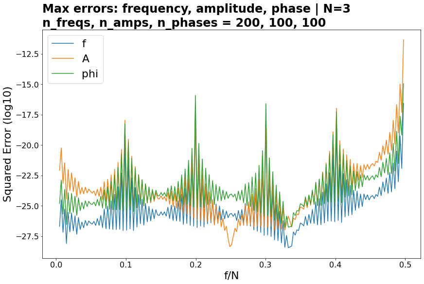
Here's the worst case, $N=3$:

These are maximum squared errors for per a given frequency.

  • Frequency (fractional) is swept 0 to 0.5, skipping integers per numeric instability of the specific implementation used (which can be overcome, and integer $f$ is the most trivial)
  • Phase is linearly swept -pi to pi
  • Amplitude is swept, logarithmically, 1e-3 to 1000, and a normalized error measure is used to avoid artificially inflating the measure: (1 - A_est/A_true)**2.

Noisy

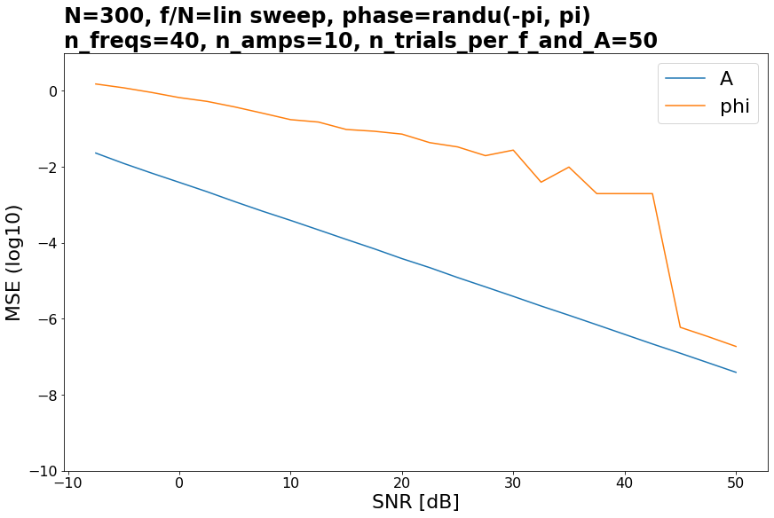
Performance improves with greater $N$, linearly with $N$ over high SNR. In fact, can be super-linear in low SNR in that the CRLB-matching (Cramer Rao Lower Bound, unbiased estimator) interval is increased. For under a second of audio:

Phase is always the most brittle, frequency least. Frequency performance, in accuracy and speed, may be state of the art - see competitive comparison.

OP's case

For OP's setup, except nudging the frequency a little (for aforementioned reasons) to 30.1, and randomizing phase, the results are

MSE: A=1.73e-05, phi=0.0513 -- SNR=23, N=300, n_trials=10000

For greater $N$:

MSE: A=1.7e-06,  phi=0.00395  -- SNR=23, N=3000,  n_trials=10000
MSE: A=1.02e-07, phi=5.77e-07 -- SNR=23, N=50000, n_trials=10000

Once the CRLB interval is matched, performance is phenomenal, and still decent otherwise.

Speed

The parameter retrieval step is $O(1)$ for all parameters. Hence the overall algorithm is just $O(N\log(N))$, FFT + absolute argmax. Interestingly, this faster than certain popular $O(N)$ algorithms - note, $O(N)$ means the full cost function (bound) is $c_0N + c_1$, and FFT's $c_0$ is low.

The method

A Two Bin Solution, by Cedron Dawg.

Notes

  • $N=2$ is doable for complex sines, that have a total of 4 datapoints. Hence Hilbert transform of pre-sampled signal is an option (analytic signal).
  • Noiseless case: if accounting for numeric precision, $N=3$ is the best case, since FFT suffers the least error. $N=3$ is worst in that we have the least possible information to work with, and any estimators (as opposed to exact solutions) suffer greatest error.

Code

Available at Github.

$\endgroup$

Your Answer

By clicking “Post Your Answer”, you agree to our terms of service and acknowledge you have read our privacy policy.

Not the answer you're looking for? Browse other questions tagged or ask your own question.