5
$\begingroup$

From what I have studied so far I have understood that the benefit of a lock in amp is its ability to resolve the amplitude of a signal which is deep into noise.

I was wondering if the same concept can be used in order to resolve the amplitude of a signal which is very close in frequency to a higher amplitude signal, assuming that your amp can lock precisely to the frequency under consideration.

Let's assume that the low amplitude signal under consideration has frequency of 12,5 Hz and there is exist a high amplitude signal (e.g 40db higher) at frequency of 12Hz, does the lock in amp have the ability to estimate this amplitude?

Any thoughts?

$\endgroup$
2
  • 1
    $\begingroup$ Maybe your can check it out using simulation softwares: compadre.org/AdvLabs/items/detail.cfm?ID=13360 and this terpconnect.umd.edu/~toh/models/lockin.html $\endgroup$
    – MimSaad
    Commented Sep 11, 2016 at 16:01
  • $\begingroup$ If you actually know the frequencies then you can filter or convert the signal of interest to DC (mixing) and do low-pass filtering. As I recall a lock-in amplifier works for noise interference but not so well for coherent interference. In that case, you have to tune it carefully and it becomes a filter; although perhaps a good one. $\endgroup$
    – rrogers
    Commented Sep 13, 2016 at 17:58

2 Answers 2

3
$\begingroup$

The answer to your questions is yes, at least for the ideal situation. My simulation is presented below, with the following assumptions: 1) the small signal is a sinewave at 12.5 Hz, with 10 mV peak amplitude, 2) the large interfering sinewave is at 12 Hz, with 1 V peak amplitude, 3) the noise is additive, white, Gaussian and has $\sigma$ = 0.1 V, 4) the RC LPF is first order, with RC = 10 s, 5) the N runninmg integration has N = 1200, i.e., 1 period of 0.5 Hz (see below), 6) the simulation has 600 points (samples) per second. The simulation model is shown below:
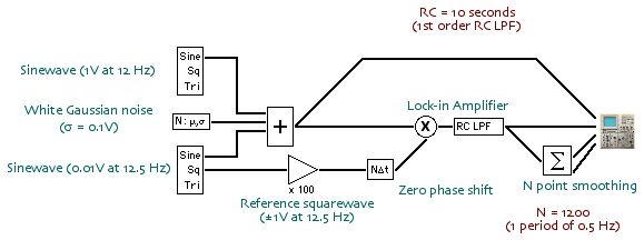
Model screenshot

The lock-in amplifier (LIA) is simply the multiplier and the RC LPF. (Of course, this is the simplest version!) The reference waveform is a squarewave exactly (deliberately) synchronized with the signal waveform. Since the frequency and phase of the signal sinewave are known, all that remains is to estimate the rms value, which is $(2/\pi)$ times 10 mV, i.e., about 6.366 mV.

The next figure shows the raw input, for the first 2.5 s, to the LIA:
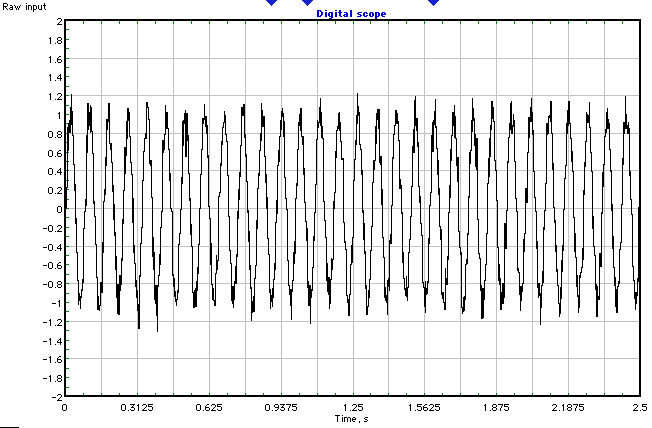
Raw LIA input waveform

The next figure shows the LIA output (cyan), the long term average (red) and the N = 1200 point running integration (green).
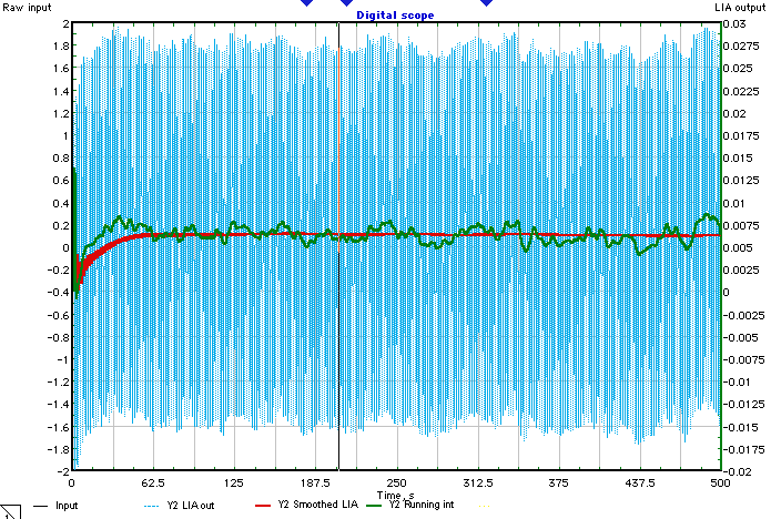
LIA outputs 1

The last figure shows the last 20 seconds of the previous figure's results (same colors for the respective outputs).
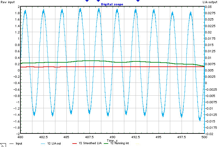
LIA outputs 2

The final value (at t = 500 s) of the long term average (red trace) was 6.22 mV and the final value of the N = 1200 point running integration (green trace) was 6.39 mV. Note in the last figure that the noisy sinewave is at 0.5 Hz, i.e., the difference frequency between the 12.5 Hz squarewave reference frequency and the 12 Hz interfering sinewave. The sum frequency, at 24.5 Hz, was largely attenuated by the RC LPF, since the -3dB frequency was roughly 0.016 Hz

Note added: The product of the 12.5 Hz signal sinewave and 12.5 Hz reference squarewave generates a sum frequency of 25 Hz (largely attenuated by the RC LPF) and 0 Hz, i.e., DC. The RC LPF passes that without attenuation. Also, it is easy to replace the simple RC LPF with a higher order low pass filter having steeper roll-off. This was not necessary in this simple example, but if the interfering sinewave had been closer to the signal sinewave, or if the interfering sinewave had some frequency jitter, then a better LPF would be needed.

$\endgroup$
0
$\begingroup$

Lock-in amplifiers work precisely because they measure the amplitude of a signal at a very particular (i.e. narrow band) frequency, and phase (though some automatically will measure both phases for you). If you have a narrow band signal with an SNR much less than one, the noise is still spread around a lot in frequency space. By picking that one narrow frequency and ignoring everything else, you throw out 99.99...% of the noise. As long as your signal is very narrow band (all concentrated at that exact frequency),then you don't throw away any signal. So the SNR goes up by 10^3-10^6, and suddenly it's good enough to measure your signal.

So, the whole point is you need a narrow band signal, and you need a frequency reference centered right on the frequency of what you are trying to measure. In the case you presented you have a good signal A, and a bad signal B that is offset from reference A. The offset means you can't use A. But, if you know exactly what the offset is, you could generate a third signal C, and lock it to A at the known offset (simple enough, but beyond the scope of this answer), and then, yes, you could use lock-in amplification to measure B using C as a reference.

$\endgroup$

Your Answer

By clicking “Post Your Answer”, you agree to our terms of service and acknowledge you have read our privacy policy.

Not the answer you're looking for? Browse other questions tagged or ask your own question.