3
$\begingroup$

Consider the controlled dynamical system $\dot{x}_t = f(x_t, u(t-\tau_{sd}))$, where $0<\tau_{sd}$ denotes the time delay caused by sampling. It is intuitively clear that the time delay caused by sampling is a function of the sampling time interval $T_s = \frac{1}{f_s}$, where $f_s$ is the sampling frequency, that is $\tau_{sd} = \tau_{sd}(T_s)$ and that $\tau_{sd} \leq T_s$. Assuming that computing the control takes half the sampling time interval and presumably based on real-world experience, we can approximate that $\tau_{sd} \approx \frac{T_s}{2}$ as stated in the notes at this link by @TimWescott who is a contributor on the platform dsp.stackexchange.com.

In the process of designing the controller, clearly we should choose the sampling frequency to be higher than the Nyquist sampling frequency $2f_{sys} < f_s$, where $f_{sys}$ denotes the highest frequency of the system, so that $$\frac{1}{f_s}=T_s < \frac{T_{sys}}{2} = \frac{1}{2f_{sys}},$$ where $T_{sys}$ denotes the shortest time period associated with the system. In the case that we choose $f_s = f_{sys}$, the associated phase delay caused by the sampling delay at the frequency $f_s$, based on the first order time delay (FOTD) model $\mathrm{e}^{-s\tau_{sd}}$, would be $$\omega_{sys} \cdot \tau_{sd} = 2\pi f_{sys} \cdot \tau_{sd} = 2\pi f_{sys} \frac{T_s}{2} = 2\pi f_s \frac{T_s}{2} = \pi = 180^{\circ},$$ where $\omega_{sys} := 2\pi f_{sys}$. However, if we choose $f_s = 10\cdot f_{sys}$, then the phase delay associated with the sampling time delay based on the FOTD model at the frequency $f_s$ is $$\omega_{sys} \cdot \tau_{sd} = 2\pi f_{sys} \cdot \tau_{sd} = 2\pi f_{sys} \frac{T_s}{2} = 2\pi \frac{f_s}{10} \frac{T_s}{2} = \frac{\pi}{10} = 18^{\circ}.$$ Therefore, the rule of thumb prescribed in the notes at the link provided earlier is to apply a sampling rate of $10$ or $20$ times the desired bandwidth of the controller.

Is there a cleaner way of arriving at the approximation $\tau_{sd} \approx \frac{T_s}{2}$ used in the line of reasoning above? Further, are there any other critical issues which are not addressed in the design logic stated?

$\endgroup$
4
  • $\begingroup$ You could probably look up Robust control. $\endgroup$
    – Ben
    Commented May 20, 2022 at 0:53
  • $\begingroup$ @Ben thanks for the suggestion. If possible, please let me know about any specific references to point me in the general direction. Thanks! $\endgroup$
    – kbakshi314
    Commented May 23, 2022 at 17:03
  • $\begingroup$ "Assuming that computing the control takes half the sampling time interval and presumably based on real-world experience, we can approximate that $\tau_{sd} \simeq \frac{T_s}{2}$" Actually, that's assuming that the control is instantaneous, because if you look at all the moments in continuous time, the average delay is $\frac{T_s}{2}$. Computation time just adds to that. $\endgroup$
    – TimWescott
    Commented May 23, 2022 at 21:28
  • $\begingroup$ @TimWescott I understand the part of the comment about the computation time but do not understand the latter, which is what the OP is about. Specifically I do not understand the comment ''if you look at all the moments in continuous time, the average delay is $\frac{T_s}{2}$'. I appreciate your answer and have been re-reading your notes as well as the excellent answer by '@DanBoschen' last week. I hope you can address the lack of clarity still persisting regarding the quantity $\frac{T_s}{2}$. Also, thanks for your details notes online, they are truly helping practicing engineers out there. $\endgroup$
    – kbakshi314
    Commented May 31, 2022 at 23:39

2 Answers 2

2
$\begingroup$

One primary consideration for the choice of sampling rate in discrete time control systems is based on Nyquist sampling requirements with respect to the transfer functions desired. This is similar to the consideration of sampling rate for the implementation of digital filters.

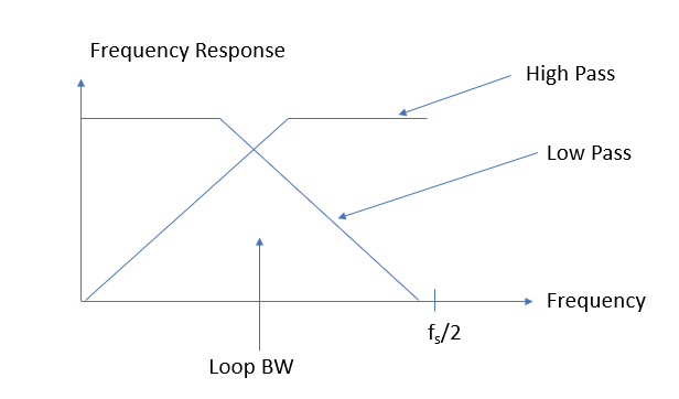
Consider a phase lock loop of a voltage controlled oscillator where the transfer function from reference to output is a low pass function while the transfer function from VCO phase noise to output is a high pass function. By integrating a high quality reference that has better phase noise performance close in (where a low pass would be ideal) with a VCO that has better phase noise further out, we achieve the best of both worlds by locking the VCO to the reference. Ultimately with consideration to phase noise optimization alone we choose the loop bandwidth to be the cross-over point in the phase noise performance: close in we get the improved phase noise of the reference (and longer term stability which is really close-in phase noise) through the loops low-pass function from reference to output, and further out we get the improved phase noise of the VCO through the loops high pass function from VCO phase noise to output.

Knowing this, if we are to implement a discrete time controller, we choose the sampling rate sufficient to implement such transfer functions. I strive to have the loop update rate to be at least 5 to 10 times to loop bandwidth, more if I need to have more frequency range to take advantage of the phase noise performance of the VCO (in this example), and less if that isn't of interest and what to concentrate more on the performance of the reference.

I show this further with the help of the graphic below:

Loop Transfer function

The closed loop will be a two port filter from any input to any output. So similar to the considerations of the sampling rate for any filter, if the Loop BW moves closer to the Nyquist boundary of $f_s/2$ where $f_s$ is the loop update rate, the rejection ability of the low pass will be limited (as given by the order of the loop and the transition bandwidth between the loop BW (cut-off) and the Nyquist frequency. Ultimately I will give consideration to the loop update rate based on the order of the loop and the requirements for rejection and loop bandwidth with these factors in mind.

As for effects of true time-delays, this is considered as part of the loop filter design for stability and increasing the sampling rate reduces the decrease in phase margin that would result due to the time delay. What we consider directly is that the Fourier Transform of a delay in time is a linear phase in the frequency domain. Specifically the delay in time will have a frequency response that is 0 dB in magnitude for all frequencies (no change in magnitude) and a phase response that has a negative slope. For example a delay of one sample at a given sampling rate will have a phase response that goes from $0$ to $-2\pi$ radians as the frequency goes from $0$ to $f_s$ where $f_s$ is the sampling rate. A fractional sample delay would have a proportionally smaller slope. With this in mind we consider the Nyquist Stability criterion which uses the open loop magnitude and frequency response to determine stability. A subset of this criterion that covers many cases that is well known is the magnitude and phase response of the open loop transfer function as a Bode plot: if the phase is more than 180 degrees when the gain goes through 0 dB, the system will be unstable. So with these points in mind we see how the linear phase that is added to the open loop response from a time delay will decrease the phase margin needed for stability (and itself can make the system unstable). Increasing the sampling rate decreases the added phase shift at the 0 dB crossing and is one approach to improve stability. More directly, this linear phase that is added is considered in the loop filter design where added zeros can decrease the increased phase from the time delay, and/or sampling rate can be increased.

$\endgroup$
2
  • $\begingroup$ Thanks for the answer. Although I understand and appreciate your explanation, I humbly submit that the answer does not address the primary concerns raised in the OP. For instance, the FOTD model pure time-delay does not find mention in the answer in addition to the related concerns based on the link provided. $\endgroup$
    – kbakshi314
    Commented May 23, 2022 at 19:59
  • 1
    $\begingroup$ @kbakshi314 thank you - I can add the time delay aspects as that is straightforward $\endgroup$ Commented May 23, 2022 at 20:00
1
$\begingroup$

Is there a cleaner way of arriving at the approximation $\tau_{sd} = \frac{T_s}{2}$ used in the line of reasoning above?

Not really. Basically it's kinda true, usually. If you're working on something where you need to know the effect precisely, then you can't use the approximation -- you're much better off modeling the plant behavior in discrete-time, doing your control system design there, then circling back to make sure the system works correctly in continuous-time.

Is there a cleaner way of arriving at the approximation τsd≈Ts2 used in the line of reasoning above?

And -- even though I recommended that rule of thumb -- it is also an approximation. There's a tradeoff between the precision of control and both the sampling rate and the complexity of the controller.

So if you can get away with coarser control you can use a lower sampling rate and a simple controller, or if you're stuck with a lower sampling rate then you can -- sometimes -- get away with it using a more complicated controller.

OTOH, really precise control often means sampling fast, and accepting the fact that you need to use wider data paths in your controller to maintain the necessary precision.

$\endgroup$

Your Answer

By clicking “Post Your Answer”, you agree to our terms of service and acknowledge you have read our privacy policy.

Not the answer you're looking for? Browse other questions tagged or ask your own question.