0
$\begingroup$

I want to generate a pseudo-random bit stream in MATLAB in a given frequency band for PSK Modulation. I am using the idinput function to generate the bit stream:

u = idinput(2^17,'prbs',[0.8 1],[0 1]);
figure(1);
[psd2,w] = pwelch(u,blackmanharris(2^17/8),[],[],1e9,'onesided');
semilogx(w,10*log10(psd2/2));grid on;

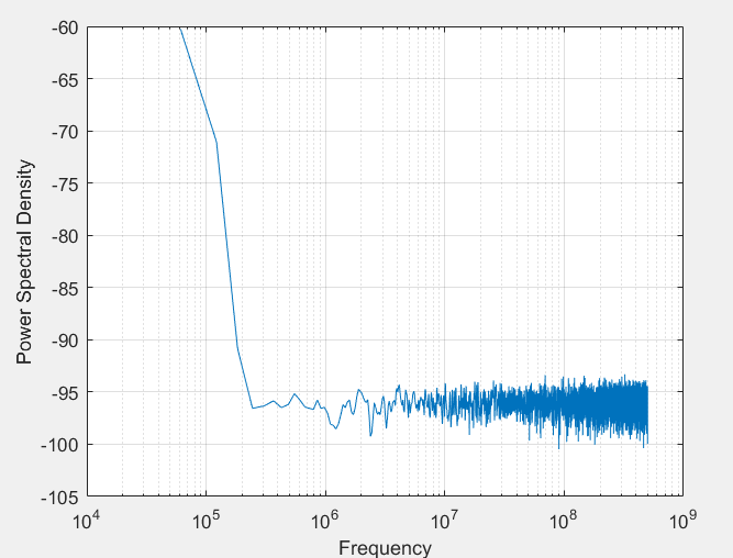
I want to use minimum a bit rate of 0.8GHz and want the bit steam in the frequency band from 0.8GHz to 1GHz. But when I check the Power Spectral Density, I see that it is flat for the whole band until 1GHz (with a DC component coming). enter image description here

What is wrong with this code? How can I make the bit stream restrict to a given frequency band?
I want to have this frequency band to be within a modulation bandwidth for the PSK transmitter.

$\endgroup$
4
  • $\begingroup$ You're confusing things: a bit stream isn't "in a frequency band"; it's a stream of bits, nothing more. You generate a bitstream, QPSK-Modulate that, then mix that up to a frequency band. But, hint, the main result from the last 100 years of wireless communication theory is that your linear, time-invariant passband channel can equivalently be represented as a baseband channel, and that for all modelling purposes, it makes no sense to mix up. $\endgroup$ Commented Apr 4, 2020 at 9:56
  • $\begingroup$ @MarcusMüller Thanks for the explanation...Could you tell me why the idinput is giving me flat response even though I specify a band. $\endgroup$
    – sarthak
    Commented Apr 4, 2020 at 10:06
  • $\begingroup$ again, you're not specifying a band. You're specifying the inverse length of the PRBS. Read the idinput documentation closely. $\endgroup$ Commented Apr 4, 2020 at 10:09
  • $\begingroup$ @MarcusMüller Thank-you I understand now... But then for carrier tracking loop we need to have a PLL with loop bandwidth smaller than the modulation bandwidth of the symbols. How can I generate symbols which are within a modulation bandwidth? $\endgroup$
    – sarthak
    Commented Apr 4, 2020 at 10:34

1 Answer 1

2
$\begingroup$

You are attempting to simulate an RF signal directly at it’s carrier frequency which will require much more processing so is not recommended. You can achieve the same results by simulating everything at its equivalent complex baseband signal due to the linear properties of the underlying frequency translation. Equivalently everything in your simulation model (IF bands, channel models etc) can/should all be at complex baseband equivalent representation (the analytic signal).

That said, to do what you are trying to accomplish with either method, you would first create the complex modulation signal mapping your data bits to PSK symbols; for example for 8 PSK 3 bits map to every complex signal such as 000 could become $e^{j\pi/4}$, 111 could become $e^{j5\pi/4}$, etc- any mapping you choose but typically “grey coded” such that adjacent symbol locations only change by one bit.

This sequence which is then sampled only 1 sample per symbol then needs to be up sampled to support implementing pulse shaping (2 samples per symbol would be sufficient but in implementation more samples here can simplify later filtering).

This now represents the complex baseband signal with pulse shaping and if 2 samples per symbol the represented spectrum from a PSD would extend from $-f_S/2$ to $+f_S/2$ where $f_S$ is the symbol rate. (Thus If oversampling more this frequency range can be extended further).

This shows the SIGNIFICANT advantage to doing all simulations at baseband - to now continue to to simulating at a carrier frequency at 900 MHz directly you would need to increase the sampling rate to be greater than the carrier frequency plus half the signal bandwidth plus some margin if completely a complex signal or twice that if simulating a real signal such that you want to model each carrier cycle. There is no reason to do this since everything that carrier is doing can be represented at complex baseband.

But if you still wanted to, against my advice, you would first interpolate the baseband waveform to this much higher rate and then multiply the signal by the carrier frequency ($e^{j\omega_c t}$ if complex or $\cos(\omega t)$ if modeling a real carrier).
$\endgroup$
4
  • $\begingroup$ Thank-you for your answer...As you said if I take the complex baseband signal its PSD would extend from -fs/2 to +fs/2. But what I don't understand then is how can we perform the carrier recovery then? Because in your answer here, you said that the loop bandwidth of the PLL needs to be lower than the modulation bandwidth or symbol rate. But if we have low frequency components in the signal itself, it will also be filtered by the PLL. $\endgroup$
    – sarthak
    Commented Apr 4, 2020 at 11:54
  • $\begingroup$ How do we ensure then that the PLL doesn't filter the data only the noise. Sorry for asking similar questions but I am new in this area and I wanted to have a model which gives me some specs for the PLL of the tracking loop. $\endgroup$
    – sarthak
    Commented Apr 4, 2020 at 11:54
  • $\begingroup$ Hi Sartak- They want to avoid discussion here but keep the comments specific to the Q&A for the post. I think I answered that in the post I linked to you elsewhere, if not answered there, ask your question under that posting. $\endgroup$ Commented Apr 4, 2020 at 11:57
  • $\begingroup$ Sir...I have asked it as a separate question here...please take a look if you have time. $\endgroup$
    – sarthak
    Commented Apr 4, 2020 at 14:56

Your Answer

By clicking “Post Your Answer”, you agree to our terms of service and acknowledge you have read our privacy policy.

Not the answer you're looking for? Browse other questions tagged or ask your own question.