0
$\begingroup$

As explained in the answer here, for the symbol timing recovery loop we need to keep loop bandwidth sufficiently below the modulation bandwidth of the signal so as to avoid the filtering of the signal itself.
But when we send a random sequence of bits the corresponding baseband signal will contain frequencies from $-\frac{f_s}{2}$ to $+\frac{f_s}{2}$, where $f_s$ is the symbol rate.
Since the signal has spectrum even at low frequencies, how can we ensure that the signal will not be filtered by the timing recovery loop?
I am asking because of the following reason:
1. I generate the PSK modulated data and add phase noise on it

dataMod = pskMod(dataVec, 8, 'gray');
tx_out = dataMod.*exp(1i*ph_out);

Here, the ph_out is the phase jitter signal and dataMod is the PSK modulated signal of the dataVec symbol stream.
2. I pass the phase of the data to the carrier recovery loop:

pll_out = pll(angle(tx_out), 0.005, 1e-6, 1e-3, 1);
pll_out1 = pll(ph_out, 0.005, 1e-6, 4e-3, 1);
pll_out2 = pll(angle(dataMod), 0.005, 1e-6, 1e-3, 1);

I create three different outputs, pll_out is the loop output with the complete signal, pll_out1 is the loop output with only the phase noise as input and pll_out2 is the output with only the signal (without noise) as the input.

I see the following at the output of the tracking loop:
1. The power spectral densities for input and output phase noise:
enter image description here

From this, I can see that the low frequency phase noise is getting filtered as expected.

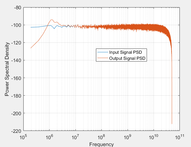
  1. The power spectral densities of input and output signal: enter image description here

From this, it is seen that the signal power at low frequencies is filtered. But because of this filtering additional "noise" or "distortion" (whatever is the correct term) causes the following PSD at the output (yellow): enter image description here
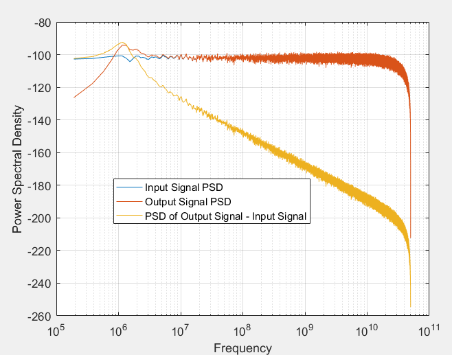
The frequency roll-off is explained very well by Dan here. But somehow now, the roll-off is not the problem for me.
3. The total noise at the PLL loop output is thus: enter image description here

So, although the signal distortion/noise does not affect me at high frequencies (and its roll-off doesn't matter anymore) but my low frequency noise gets degraded.
So, how can we ensure that most of the signal power is outside the PLL bandwidth?

$\endgroup$
1

1 Answer 1

2
$\begingroup$

Ultimately we are trading how much signal we lose versus how much noise (phase noise dominantly) we are rejecting along with being able to track dynamics in the overall model between trasnmitter and receiver. If I was optimizing this I would do a simulation with the actual parameters for all noise sources and expected dynamics in my system, but I start with the rule of thumb as I suggested in this other post Loop bandwidth for symbol timing recovery of using something between $R/100$ to $R/20$ where $R$ is the symbol rate. The bottom graph shows the effect of a lower cut-off frequency in that more of the symbol energy is maintained.

To see this consider the following graph showing a bi-phase signal (+1/-1) after passing through a high pass function. This also shows the motivation to not have an excessively long stream of all 1's or all 0's in the modulated data, which is one reason for data scrambling at the source (another reason is timing recovery).

sketch

The top graph shows the bi-phase signal with infinite bandwidth including DC. The issue with maintaining bandwidth to DC in the receiver is phase noise and timing drift. Ultimately the DC value that here is centered on 0 would drift as the receiver estimate of the transmit carrier shifts from true value. We use the received signal to track this, which is a high pass function. If we track too quickly, as in the second graph, we remove too much of the symbol energy since the carrier tracking loop with wider bandwidth would assume the new DC value representing the symbol is actually the carrier, thus removing it. A very long stream of 1's or 0's in a row would have the same effect.

So the answer is to understand first what is the longest possible run of symbols that would not change in the receiver and then choose a loop bandwidth that minimizes the amount of symbol energy lost over that time interval, while ensuring the bandwidth is fast enough to track changing conditions and minimizing noise from low frequency sources such as phase noise.

As a rough measure of the impact of a loop BW using a loop BW of $R/20$, where $R$ is the symbol rate, consider that the single sided bandwidth of a properly pulse shaped waveform is slightly over $R/2$. If the loop BW was $R/20$ the SNR loss would approximately be 0.46 dB from tracking loss alone:

$$10log_{10}\bigg(1-\frac{R/20}{R/2}\bigg) =10log_{10}(0.9) = -0.46 dB $$

This can be decreased by lowering the loop bandwidth further (-0.18 dB for $R/50$), but you need to then see if you are adding more noise to this from the increased phase noise that would be added from the local oscillator and other jitter sources (sampling clock) as I show here PLL for Phase Demodulation and Carrier Tracking , or if the dynamics in the system (Doppler for a moving transmitter or receiver for example) are changing faster than this can track.

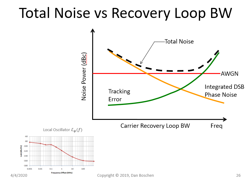
This graph I have shows the basic concept and to consider the optimization problem, and as depicted there typically is a long shallow bottom in choosing the carrier recovery loop bandwidth where the noise is minimized. In a properly designed receiver, amplified thermal noise would be the dominant noise source (the goal of analyzing the cascaded noise figure), and the carrier loop bandwidth should be within this region where that applies. LO and jitter noise sources are typically set to be 10 dB or more below this noise level so as to add only a small contribution to the overall noise figure budget. As we see in this graph, if we however set the loop bandwidth too low, the LO/Jitter contributed noise sources will start to dominate. If we set the loop bandwidth too high, then tracking noise (which is tracking out the modulation as I show above as well as self-noise that can be originate from our carrier tracking loop) will start to dominate. Overall this is a system design challenge as it considers all noise sources in both the analog and digital domain and is a great example of how such mixed signal implementations cannot be designed individually in a vacuum.

optimizing loop bw

$\endgroup$
15
  • $\begingroup$ Thankyou for the answer.So if I summarize you mean that the loop bandwidth has to be sufficiently lower than the longest stream of 0's or 1's which is ultimately the minimum frequency component present in the signal. Correct? But is it possible to generate such data in MATLAB? Because my signal has high power even inside the loop BW. And however small a loop BW I choose, ultimately the noise performance at the loop output is degraded when compared with noise of the sent data because signal is flat and always creates inband signal noise. So it looks as if tracking loop is degrading performance $\endgroup$
    – sarthak
    Commented Apr 4, 2020 at 15:56
  • $\begingroup$ Is it possible to generate such bitstream in MATLAB which has low energy at low frequencies? $\endgroup$
    – sarthak
    Commented Apr 4, 2020 at 15:56
  • $\begingroup$ The longer you observe a constant for, the lower frewquency it has; In order to see DC you would need to observe a constant for infinite time. So if you have a bitstream that repeats for a long time such as 1 1 1 1 1 1 1 1 1 1 1 1 it would contain more energy at lower frequencies. $\endgroup$ Commented Apr 4, 2020 at 16:02
  • $\begingroup$ In typical application a well designed system would have a bitstream representing a random sequence with equiprobable distribution (and scrambled to ensure this) so it is a reasonable assumption to assume the energy is spread evenly from DC to R/2). $\endgroup$ Commented Apr 4, 2020 at 16:03
  • $\begingroup$ But does that mean that the SNR performance (considering only phase noise) at the PLL loop output is always going to be worse then at the input (assuming the PLL loop adds no noise)? Because ultimately however small loop BW you choose, the inband signal noise (due to high pass filtering) is going to degrade the phase noise performance. $\endgroup$
    – sarthak
    Commented Apr 4, 2020 at 16:36

Your Answer

By clicking “Post Your Answer”, you agree to our terms of service and acknowledge you have read our privacy policy.

Not the answer you're looking for? Browse other questions tagged or ask your own question.