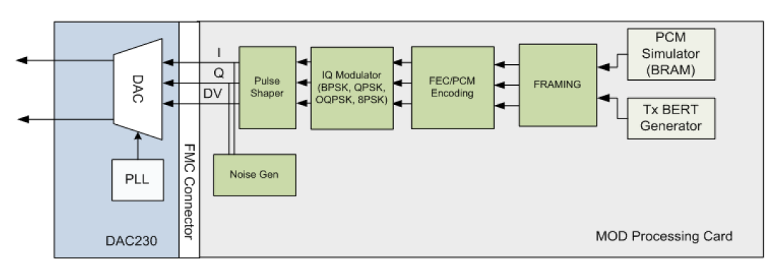
Do most modulators today match the second picture below? (Software to determine what the modulated waveform should look like for whatever scheme, then feed a stream of bits representing the voltages of that signal to a DAC to produce the physical signal? (So there would be no actual carrier signal out of an oscillator being physically mixed with a modulating signal.?))
Since the second picture is only one part of the modulator, no.
It's the baseband part of something very specific (you took that picture from somewhere where you ignored and didn't understand the context!); yes, digital baseband creation prior to using the mixers from your first picture are very common, but they are by far not the only architecture. So, "all": no. "Many: yes.
Does pretty much any demodulator today just give the received signal to a ADC and do all the demodulation in software? (No actual hardware mixers and filters to do correlation and pull bits out as voltages?)
No, that is very rarely the case; direct sampling receivers as you describe them are only used there the carrier frequency is very low, or where unusually excellent band-pass filters allow for a bandpass subsampling. You can, without much worries, keep these in mind as "advanced concepts".
If a modem is doing the modulation/demodulation in software like the second picture below, what is it called?
Nothing in your second picture indicates any of this is done in software. It might be done in digital hardware, or a software/digital hardware combination. Be careful when conflating "digital" with "software". They are not the same thing! "Digital" just literally means "discrete in time, and discrete in values", and software is one thing that can deal with such things, but math just as much. But you cannot "run" math. But you can run both software and digital hardware, and you can even do things that your "digital" math motivates in analog hardware.
So, please be more careful about your terminology.
The line between "software modem," "software defined modem," and a couple other terms I've heard seems fuzzy to me
That's because the line is fuzzy. Context matters! Different terms mean different things in different texts, and you usually need to read the text in full context. This is true for any technical term – as communications engineers, we do have the luxury that most things are cleanly defined by math, but "English technical terms" is very much a human concept, and different humans mean different things :)
And calling it a "digital modem" seems completely unhelpful, since any modem processing a digital comms scheme would be digital and would be handing a baseband pulse stream of bits to some output at the end either way.
But here you're again being unnecessarily imprecise: Digital vs Analog is completely orthogonal to Baseband vs Passband, to Pulse vs Stream.
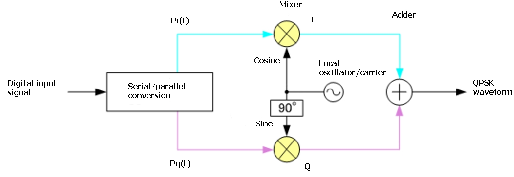
Below is the basic QPSK modulator, showing execution of most of the steps (especially modulation of the carrier) as being done in circuits.
This is a pretty bad drawing. I'd honestly recommend you erase it from your memory; it means "binary input" where it says "digital input"; it confused "serial/parallel" conversion with "mapping to +1 / -1 on the I and Q components", and it completely forgets the pulse shaping, which you would very much apply prior to modulation onto the carrier. It also hides the fact that there's a DAC somewhere in the white box, which contributed to your confusion! And it uses the term "adder", which is really a term we typically use when we add numbers digitally, not sum analog signals.
(I'm a bit angry at that diagram, sorry; this is nothing against you. I just used to design exam questions of the kind "please draw all components necessary to implement a QPSK modulator with a well-defined pulse shape, based on the concept of quadrature and inphase modulation. Label all components.", and this figure would have made like maybe 4 out of 10 possible points in that exam, on a good day. Any alternative implementation, even with errors, could have gotten a student more points, as long as it demonstrates the ideas being understood; and this diagram betrays that whoever drew it only remembered the thing about a 90° phase shift, and then threw in terms they heard in other parts of their lecture. And you're supposed to learn from that? That's unfair to you.)


