In addition to the good points Marcus has made in his answer, I want to add that there are other DAC topologies specific for doing this more efficiently.
The OP is correct that a traditional (Non-Return to Zero or NRZ) DAC will suffer from passband roll-off due to the staircase reconstruction, in addition to any other bandwidth limitations of the DAC analog output circuits. This doesn't mean the output can't be physically created, rather it just means there is an attenuation due to that roll-off. The output still has all the frequencies as we get with the case of an ADC (based on the digital signal being a stream of weighted impulses).
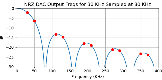
I show the expected result in the plot below for a NRZ DAC with the OP's case of creating a 50 KHz sine wave output with a sampling rate of 80 KHz. Just as with an ADC, the sampled spectrum will be periodic repeating around every multiple of the sampling rate. For a real sinuosoid at frequency $f_n$ the output frequencies will be $fout = Nf_s +/- f_n$, where $f_s$ is the sampling rate and $N$ is a positive integer. With a 80 KHz sampling rate, 50 KHz is created by $N=1$ and $f_n=30$ KHz. Thus we get a 50 KHz output by digitally creating a 30 KHz sinusoid sampled at 80 KHz, and bandpass filtering the output in the range from $f_s/2$ to $f_s$ which is referred to as the "Second Nyquist Zone".
All the output frequencies in the frequency range plotted are indicated by the orange circles and would be at $N 80 \text{ KHz} \pm \text{ 30 KHz} = [30, 50, 110, 130, 190, 210, 270, 290, 350, 370 ....] \text{ KHz}$
The attenuation due to the staircase reconstruction in the DAC is indicated in blue, and we have a predicted output level of 50 KHz that is attenuated by approximately -6.5 dB. (Note that the 30 KHz tone itself is also attenuated approximately 2.1 dB).

As introduced above, the NRZ provides a zero-order hold staircase reconstruction which can be shown to multiply the output spectrum with a Sinc function shape in frequency, with the first null at the sampling rate. This in addition to the output bandwidth of the analog output of the DAC circuit itself. The sampled system is periodic in frequency, so any particular higher frequency output can be selected with bandpass filtering but will be attenuated by the analog output bandwidth of the DAC and the Sinc shape from the staircase reconstruction.
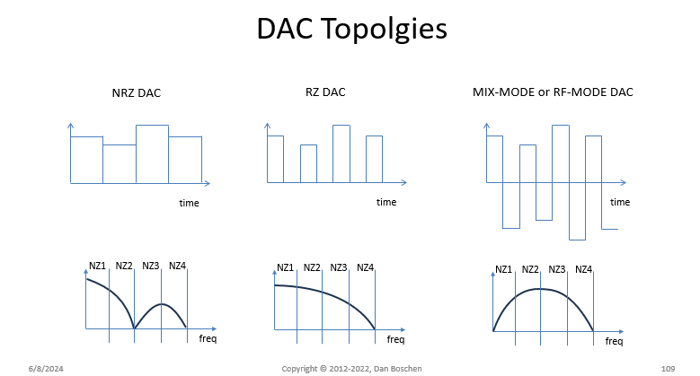
DACs for improved performance in higher Nyquist zones for direct sampling applications include Return to Zero (RZ) DACs where the output of the DAC is a pulse that is half the width of the output period instead of the full width as in the case a traditional NRZ DAC. At the expense of output power (and therefore SNR) in the first Nyquist zone, there will be a cross-over in the 2nd Nyquist zone where we gain more output power and SNR, as the effect of this is to push the first null in that Sinc shaped frequency roll-off out from $f_s$ to instead be at $2f_s$.
Another topology with even better performance for operation in the third Nyquist zone has the output toggle in polarity at half the width of the output pulse. DACs with this mode of operation are referred to as “RF-mode” by Analog Devices and "Mixed-Mode" by TI and AMD. Even other operating modes that are available are further detailed in the references at the end of this post.
A summary of the frequency responses for the NRZ, RZ, and RF mode operation are shown in the plot below. NZ1, NZ2, NZ3, and NZ4 refer to the Nyquist Zones, with the upper edge of NZ2 at the sampling rate ($f_s$):

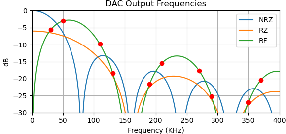
The plot below shows the resulting 50 KHz signal out of these operating modes, with the "RF-mode" resulting in the lowest loss for a 50 KHz output with an 80 KHz sampling rate. We also see from this plot that the NRZ DAC still out-performs the RZ DAC if it were to be used directly for producing a 50 KHz output, but the RF DAC is about 4 dB better.

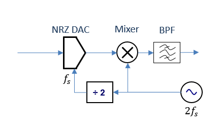
It's possible that this mode could be emulated by following a standard NRZ DAC that supports the output bandwidth with an analog mixer, with the LO driven by a 2x clock synchronized to the sampling rate $f_s$ as I draw in the diagram below.

Related Links:
Nice overview of multiple DAC mode variants:
"Operational modes of high-speed DACs: analysis and mathematical modeling, by K. K. Khramov and V. V. Ramoshov:
https://iopscience.iop.org/article/10.1088/1742-6596/1096/1/012158/pdf
Overview by ADI:
https://www.analog.com/en/resources/technical-articles/directsampling-dacs-in-theory-and-application.html
TI DAC supporting the "RF-Mode" or what they call "Mix-Mode" (This is a very expensive DAC for direct sampling applications in multi-GHz frequencies, just as an example but not a suggested part for the OP to use!):
https://www.ti.com/lit/ds/symlink/afe7954.pdf?ts=1696542130043&ref_url=https%253A%252F%252Fwww.google.com%252F


