1
$\begingroup$

I am reading Digital Signal Processing Using Matlab by Ingle and Proakis (3rd ed.)

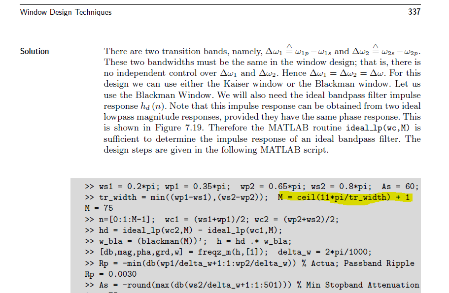
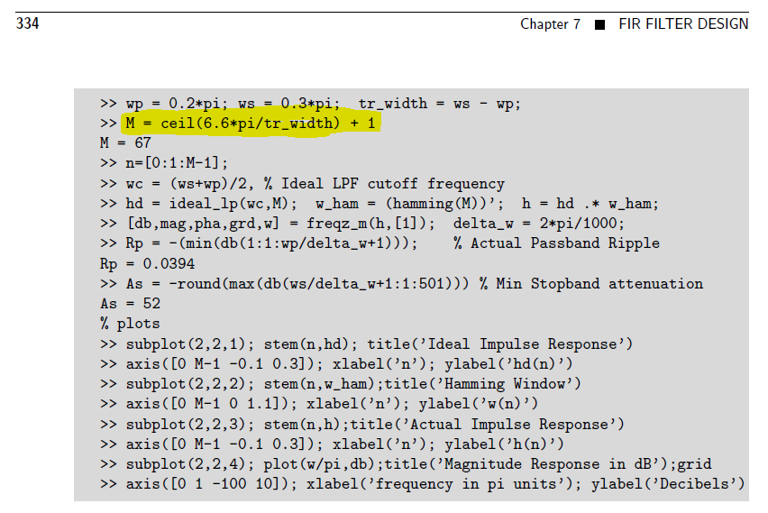
In Chapter 7, Section 7.3, I am confused why he is adding 1 to main lobe width for calculating length of window. I have attached snapshots below. First/above snap is of matlab code of example 7.8 and 2nd snap is of code of example, both snaps contain the confusing line as highlighted.

enter image description here

enter image description here

$\endgroup$
1
  • 1
    $\begingroup$ Please refrain from linking to a whole book in pdf form, unless it has been released by the authors themselves under specific terms. For an example please see here. $\endgroup$
    – A_A
    Commented Jul 22, 2020 at 8:46

1 Answer 1

4
$\begingroup$

This is just an empirical formula found by Kaiser for determining the necessary filter length for a given transition width. That formula is given as Equation $(7.30)$ on page $332$:

$$M=\frac{A_s-7.95}{2.285\,\Delta\omega}+1\tag{1}$$

I think that Kaiser came up with a formula for determining the filter order (hence without the $+1$ in the equation), and the authors of your book preferred to have a formula for the filter length, so they took the original formula and added $1$ to it.

Judging from some of your previous questions, you seem to be confused when it comes to the terms filter order and filter length. For FIR filters, filter length is the number of coefficients (taps). Filter order is the (minimum) number of delay elements necessary to implement the filter. It's just like with polynomials: their order is one less than their number of coefficients. E.g., a second-order polynomial has $3$ coefficients:

$$P_2(x)=a_2x^2+a_1x+a_0\tag{2}$$

Coming back to FIR filters, you always have

$$\textrm{filter length}=\textrm{filter order}+1\tag{3}$$

EDIT:

Note that formula $(1)$ above is valid for a Kaiser window, which I chose according to the title of your question. Looking a bit closer at the code, it becomes clear that in the first snippet they actually use a Hamming window, whereas in the second snippet they use a Blackman window. For these windows, there are other formulas for estimating the filter length. These formulas can be found in Table 7.1 (p. 330) of the book you refer to.

$\endgroup$
6
  • $\begingroup$ you wrote " For FIR filters, filter length is the number of coefficients (taps)." does it mean zero taps or non zero taps or both? $\endgroup$
    – DSP_CS
    Commented Jul 24, 2020 at 16:59
  • $\begingroup$ @engr: It's the number of taps from the first to the last non-zero tap, no matter how many coefficients in between are zero. If you have the coefficients $1,0,0,0,0,-1$ then the filter length is $6$. It's the extension of the impulse response. $\endgroup$
    – Matt L.
    Commented Jul 24, 2020 at 17:10
  • $\begingroup$ If we have another zero to right of"-1", still length will be 6? $\endgroup$
    – DSP_CS
    Commented Jul 24, 2020 at 17:16
  • 1
    $\begingroup$ @engr: It depends. If the filter is causal (and implemented in real time) then you have to count any additional delay starting from index $n=0$, because you need to implement the delay. Look at it this way: how many delay elements do you need to implement the filter? The filter length is the number of delays (= the filter order) plus one. $\endgroup$
    – Matt L.
    Commented Jul 24, 2020 at 17:23
  • $\begingroup$ In above MATLAB code, M=ceil(11pi/tr_width)+1,but in your answer your first term is something different from ceil(11pi/tr_width)?? $\endgroup$
    – DSP_CS
    Commented Jun 13, 2022 at 13:44

Your Answer

By clicking “Post Your Answer”, you agree to our terms of service and acknowledge you have read our privacy policy.

Not the answer you're looking for? Browse other questions tagged or ask your own question.