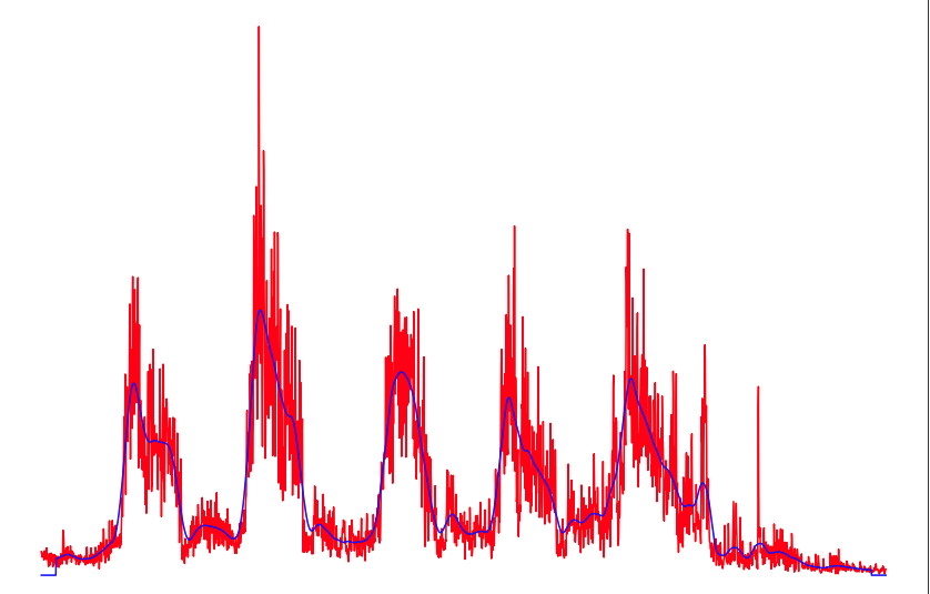
If you know the maximum frequency of your signal of interest (for example what is the time duration of the 5 cycles in your plot - then for this time $T$ the max frequency would be $5/T$... could the cycles appear faster? If so whatever the maximum rate is would be pertinent.
With that I would recommend that you design a low pass filter using the least square algorithm (firls in Matlab/ Octave and Python Scipy.Signal). This will usually out-perform any mapped filter from the analog domain (such as Butterworth, Chebyshev, elliptic etc) and provide a linear phase response eliminating any phase distortion in your resulting signal. I generally recommend for most digital filtering applications to not "copy the analog" unless you are modeling such filters specifically, given the capability of these modern direct digital filter design algorithms. You can decide on your cut-off transition band and rejection based on how many taps you want to make your filter, trading off overall delay. (You could also consider the Parks-McLellan algorithm using firpm in Matlab and remez in Octave/Python but I prefer least-squares error criterion over the minimax for most applications).
This would also out-perform a moving average in all but white noise conditions. The frequency response of the moving average approaches a Sinc function as the number of samples averaged increases, with a first null at $1/T$ where $T$ is the time length of the moving average. As a Sinc function it has multiple sidelobes with peaks going down relatively slowly at $1/f$ thus is a poor filter against high frequency components that may be present.
Further if you had a low frequency limit you could consider a bandpass for further noise rejection, but the transient result from doing this may be unacceptable.

