0
$\begingroup$

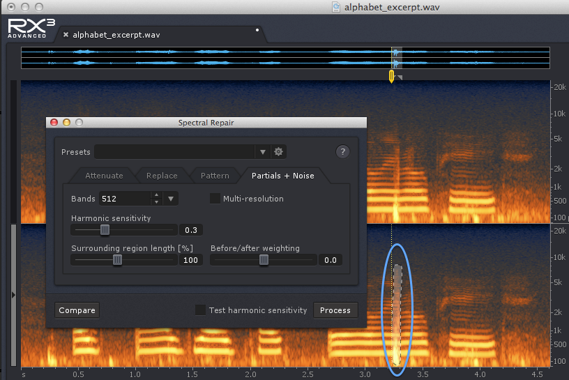
How does iZotope RX handle the FFT (i.e. how does it manage to perform those processes in the frequency domain without creating glitches) since its able to e.g.

  • Apply another DSP process (even time-domain) into a spectral part (i.e. apply e.g. a phaser onto individual parts of the FFT).
  • Attenuate or gain spectral parts (without touching the surrounding parts).

Is it really frequency domain filtering or time domain using time domain filters?

enter image description here

I thought this kind of processing was impossible:
Why is it a bad idea to filter by zeroing out FFT bins?

$\endgroup$
8
  • 1
    $\begingroup$ Apart from the fact that probably nobody here would know the exact algorithms used in iZotope RX, it would be good if you clarified your question a bit. What do you mean by "handle the FFT"? By "apply another DSP process into a spectral part"? And how do you know that they "attenuate or (amplify) spectral parts" without affecting other frequency bands? $\endgroup$
    – Matt L.
    Commented Mar 6, 2016 at 13:34
  • $\begingroup$ @MattL. What I'm trying to figure out is whether this is really frequency domain processing or whether FFT is merely used for the display and then the actual processing (for some of the processes at least) is done in time domain. $\endgroup$
    – mavavilj
    Commented Mar 6, 2016 at 13:40
  • 1
    $\begingroup$ It doesn't really matter, equivalent processing can be performed in either of the domains. As far as the frequency domain is concerned, please see en.wikipedia.org/wiki/Overlap%E2%80%93add_method and en.wikipedia.org/wiki/Overlap%E2%80%93save_method $\endgroup$
    – A_A
    Commented Mar 6, 2016 at 13:43
  • $\begingroup$ @A_A So FFT and time domain filters have the same shape? I thought FFT would allow for far more filter shapes than time domain. Such as those more closely mimicking the spectral visual part of the sound. $\endgroup$
    – mavavilj
    Commented Mar 6, 2016 at 13:47
  • 1
    $\begingroup$ We cannot have this discussion in the comments section :) The short answer is yes. Both of the bullet points that are mentioned in your original question refer to digital filtering. This is what filters do anyway, whether in frequency or time domain. And yes, they can have any "shape" you like. Can you add a bit more in your question and then we can try at a "proper" answer. What is it that you are trying to understand exactly? What is the "problem"? $\endgroup$
    – A_A
    Commented Mar 6, 2016 at 13:51

1 Answer 1

1
$\begingroup$

Spectral Repair is more complex than just muting a handful of harmonics.

But first, let's just clarify that as far as Linear Time Invariant (LTI) systems are concerned, their processing can be applied, equivalently, either in the time domain (via the operation of convolution) or the frequency domain via either the overlap-add or overlap-save methods.

iZotope's Spectral Repair performs interpolation. That is, to remove an unwanted portion of a recording, it will try to "mimic" the characteristics of the spectrum in either ends of the unwanted region.

Consider the following image:

Railings with a uniform background

Can't we just remove the railings by copying and pasting the grass from another (and very similar) part of the image and adjust its brightness? Couldn't we even replicate how the green colour varies in the grass portions and just generate some "new" grass for the regions of the railings?

Is it going to look odd? Possibly, if it was overdone, but for small regions it may be good enough to fool the eye.

This is what the "Replace" mode (and "Attenuate") does in iZotope, but instead of grass and railing there is background noise and local disturbance.

It's not so much attenuation (or "setting harmonics to zero") as "masking" or "hiding" the unwanted sound, since it attempts to make up a good enough patch of harmonics to bury it in by "looking at" the surroundings of the disturbance.

For more information on interpolation please see this link. For an example of "learning the profile and applying a filter" please see this link and this link.

Hope this helps.

$\endgroup$
3
  • $\begingroup$ So you're claiming that RX may be manipulating the FFT bins like image pixels? $\endgroup$
    – mavavilj
    Commented Mar 6, 2016 at 15:08
  • $\begingroup$ Also, if my FFT implementation already claims to do overlap add, then I don't need to implement that myself? Can I merely process the resulting FFT bins as I wish? But what kind of techniques are used to manipulate FFT bins? $\endgroup$
    – mavavilj
    Commented Mar 6, 2016 at 15:44
  • $\begingroup$ There are 4 question marks: 1)The discussion about the image was just to illustrate the method. In iZotope and other software, the spectrogram's pixel value (probably an INTEGER) is just a representation of the FFT numeric value (probably a DOUBLE) it is not used for processing, only for visualisation. 2) No you don't 3) Yes 4) Complex time variant filtering (please see: en.wikipedia.org/wiki/Spectrogram ) $\endgroup$
    – A_A
    Commented Mar 6, 2016 at 16:11

Your Answer

By clicking “Post Your Answer”, you agree to our terms of service and acknowledge you have read our privacy policy.

Not the answer you're looking for? Browse other questions tagged or ask your own question.