I am having a problem in my current project where I need to measure different biological signals (like ECG) simultaneously.
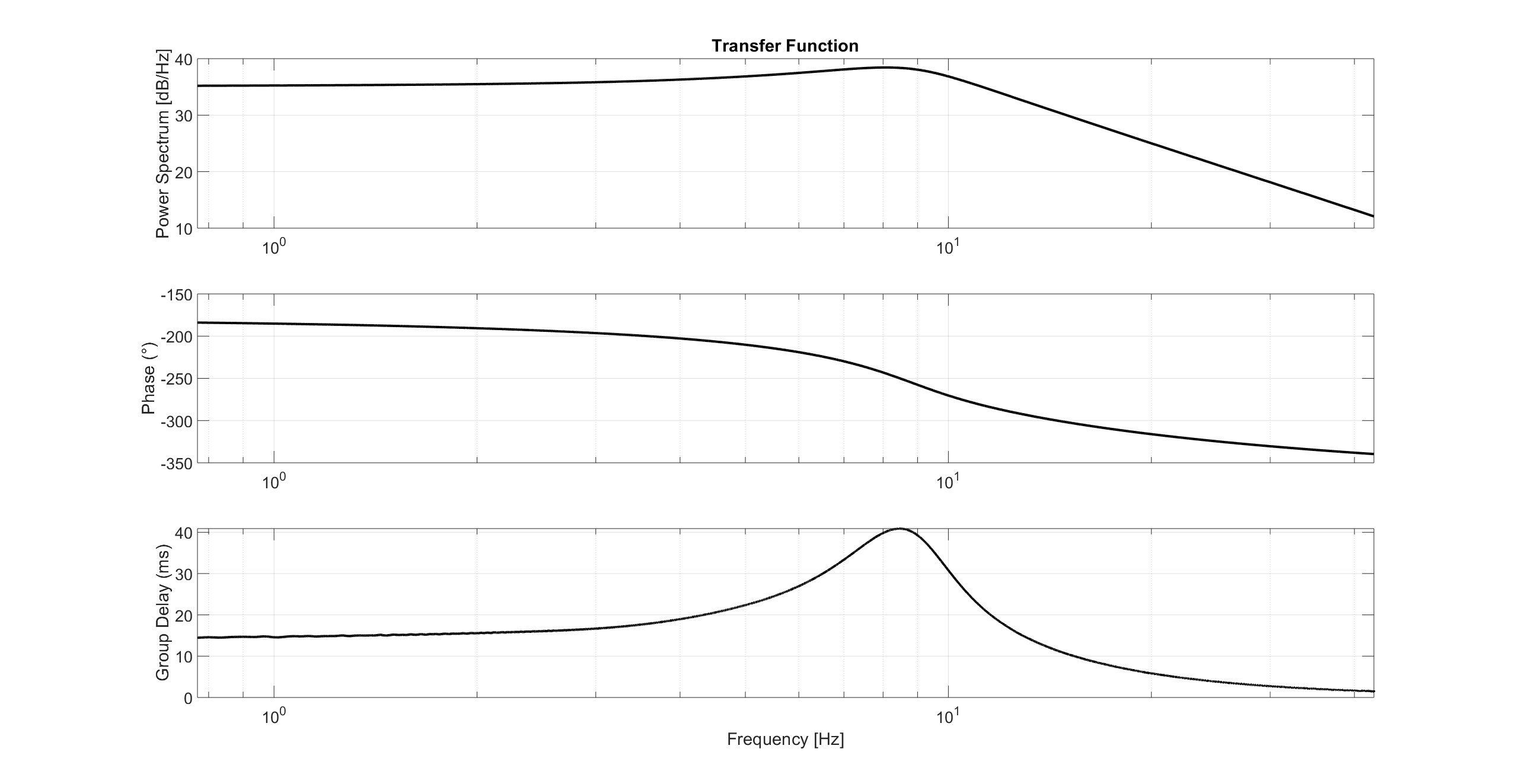
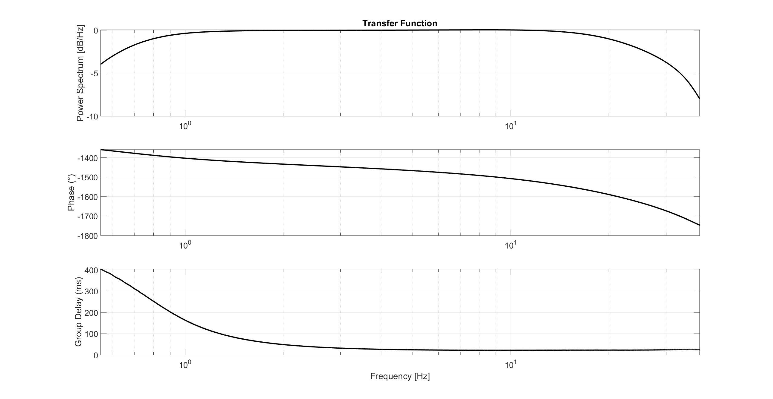
As the instrumentation hardware is developed by different people over time, they are not identical to each other. All of them has different orders of low-pass and high-pass filters before their final amplification stage. These filters are mostly concentrated around the passband of [0.5-35] Hz. I want to compensate for the phase dispersion caused by those analog filters by designing my own digital filters. I have measured the transfer functions of those channels using chirp signals, to get an idea, please check the following figure. There might be small numerical errors in the calculation of the transfer function.


Not only eliminating the phase dispersion in the individual channels but also compensating the different amount of delay of those channels is important so that I can analyze fully "synchronized" signals. So far, I have been trying to design an all-pass filter in Matlab using iirgrpdelay function. However, the created compensation filters are not satisfying. The reason for that might be the huge variation in group delay (see the first figure) between [1 15] Hz, the region I want to compensate. Increasing the order of the filter doesn't help since I mostly get the following error from Matlab:
Poorly conditioned Hessian matrix. Cannot accurately compute the optimization because either the approximation error is extremely small (try reducing the number of poles or zeros) or the filter specifications yield huge magnitude variations, such as mag=[1 1e9 0 0].
I don't want to leave the question this broad but I am asking for suggestions to design such compensation filters in the digital domain so that I can neutralize this phase dispersion and delay in the analog instrumentation.
