2
$\begingroup$

An FFT-based coarse frequency acquisition block is being tested in GNU Radio. The algorithm used can be found on the GOES satellite user manual and is summarized in the figure below. goes-acquisition The algorithm works by:
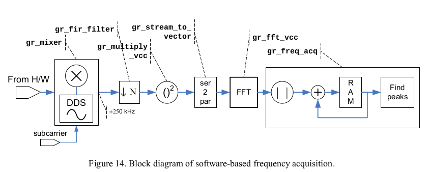
  1. Carrier detection by absolute-law, square-law or fourth-power law. Square law detector involves squaring the IQ signal while fourth-power law uses the fourth-power of the IQ signal.
  2. Finding the FFT
  3. Averaging successive FFT sequences
  4. Finding the peak by looking at 8 adjacent bins with the highest magnitude.

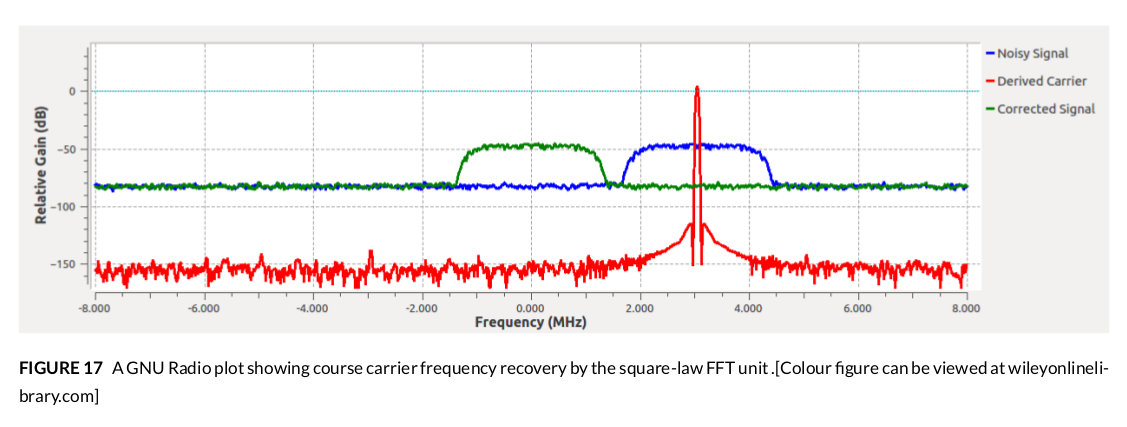
I have been able to implement the algorithm in GNU Radio, at least for BPSK. The algorithm is able to recover the carrier at all offset scenarios (offset < 10% symbol rate, offset ~ symbol rate, offset > symbol rate). fft-acquisition-gnuradio fft-acquisition-bpsk
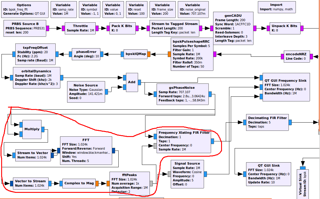
According to the GOES manual, the same algorithm should work for OQPSK, and I assume by extension, QPSK. However, the carrier derived by the algorithm for the case of QPSK is pretty bad, especially in low-SNR scenarios.

I have two questions

  1. Are there any literature sources as to how the frequency detectors (square, fourth-power) work? I have basically implemented the algorithms but I do not fully understand their mathematical derivations.

  2. Is there a more effective frequency detector for QPSK apart from square/fourth-power/absolute laws that could remedy the situation?

Regards, Moses.

EDIT

Disclaimer: Using a fouth-law as proposed by @DanBoschen resulted in expected BER performance. For all intents and purposes, the answer is already accepted. But, I have observed some behavior of the nature of FFT relating to this question. I figured there wouldn't be any need to open a new question since we are already here.

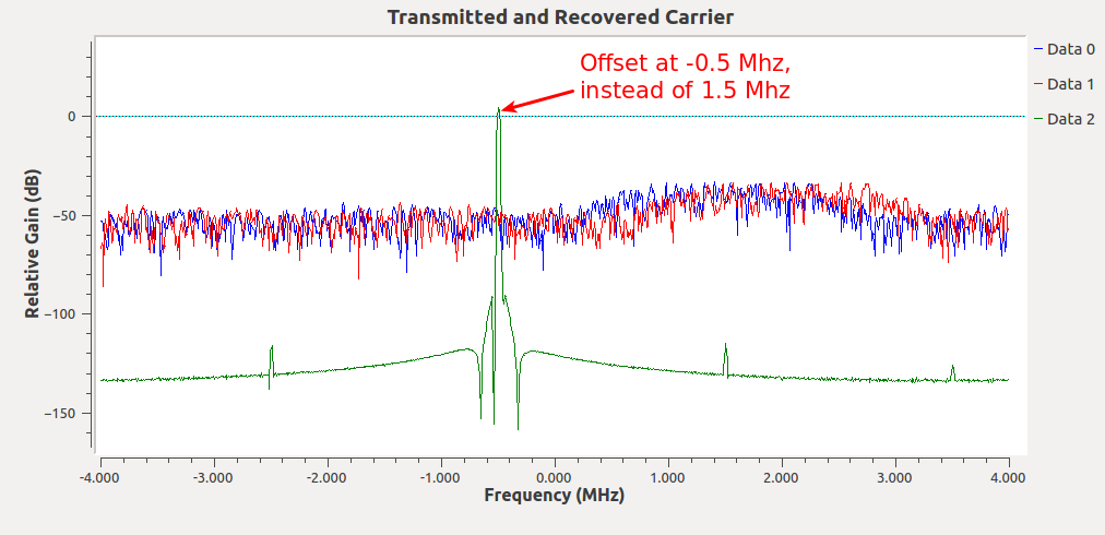
In the flowgraph, the sample rate used is 8Mhz. The fourth-law-derived carrier can be tracked from -4Mhz to +4Mhz. There seems to be an "FFT ambiguity" when the offset frequency is above $\frac{1}{8}$-th the sample rate i.e anything above 1Mhz. Taking, for example, an offset of 1.5Mhz. The fourth-law detector will create a carrier at 6Mhz, which will be wrapped to -2Mhz in the second Nyquist zone. Dividing this by 4 results into an offset of -0.5Mhz, instead of 1.5Mhz, as shown in the figure below (derived carrier in green).

We can solve this problem by simply using a sample rate which is 8x the maximum offset for the fouth-law or 4x the maximum offset for the square-law. But, of course, that's not an ideal solution. I was wondering if there are better ways.

fft-ambiguity

$\endgroup$
1
  • $\begingroup$ sorry for my late response but just noticed your additional edits now. Yes your point of the increased sampling rate is valid. I wanted to be sure you saw that I noted that in my answer and saw my references to "better ways" which I would recommend over fourth-law recovery approaches. $\endgroup$ Commented Jul 13, 2021 at 4:48

1 Answer 1

5
$\begingroup$

A square operation creates an unmodulated tone for a BPSK signal at 2x the carrier frequency (a pure tone for the case that the signal was unfiltered or rectangular pulses with perfect phase and amplitude balance in the BPSK modulation, and typically a stronger carrier with weaker sidebands in the more common filtered or pulse-shaped cases). For QPSK signals (including OQPSK) a fourth law operation is required which produces the same at 4x the carrier frequency.

This can be explained by knowing that multiplying signals causes their phases to add. So a signal multiplied by itself (square) that is modulated 0° to 180° would then become 0° to 360° which is the same as 0° (unmodulated). For QPSK the states are 0°, 90°, 180° and 270° where it can be seen that multiplying any of those phases by 4 results in 0° using the same modulo 360 operation when adding phase.

It is typical when using this approach for carrier recovery to also use a PLL to track the recovered 4x carrier in order to clean up the residual (much lower) sidebands resulting from the finite bandwidth modulated signal and then the PLL-filtered signal is frequency divided to complete the carrier recovery.

I tend not to use this approach given the higher sampling frequency required and the comparative complexity to other methods when implementing all digital systems but this would make for a relatively simple analog approach using analog frequency multipliers. I detail another approach for carrier recovery specific to BPSK, QPSK and QAM that would be in my opinion much more efficient for a digital radio implementation in this post: High modulation index PSK - carrier recovery

This is also an interesting approach by fred harris for a frequency lock loop that I believe would work for QPSK carrier acquisition with additional subsequent phase tracking: How does this FLL work?

$\endgroup$
9
  • $\begingroup$ Nice, this is neat! $\endgroup$
    – Gilles
    Commented Apr 30, 2019 at 21:07
  • $\begingroup$ Thanks, @DanBoschen for a very good explanation. If I understand correctly, using a square-law detector on a QPSK signal would result in the following modulo 360 values: $0^{o} \rightarrow 0^{o} $ $90^{o} \rightarrow 180^{o} $ $180^{o} \rightarrow 360^{o} = 0^{o} $ $270^{o} \rightarrow 540^{o} = 180^{o} $. The $90^{o}$ and $270^{o}$ don't seem to add to $0^{o}$. Could this explain why square-law suffers BER degradation for (O)QPSK (especially at low SNRs)? $\endgroup$ Commented May 2, 2019 at 14:26
  • 1
    $\begingroup$ Squaring converts QPSK to BPSK (so would still have 0 and 180 phase states). If there are a statistically equal number of each state, the carrier is suppressed, so there is no signal for the PLL to lock to, only sidebands. Only when you eliminate the BPSK modulation by squaring again do you then recover the carrier as I described. $\endgroup$ Commented May 2, 2019 at 14:29
  • $\begingroup$ Thanks, @DanBoschen for the clarification. The answer is already accepted. But, I made some new observations related to this question and added them as an EDIT. $\endgroup$ Commented May 2, 2019 at 15:48
  • $\begingroup$ Yes you are getting the expected result as you described (2nd Nyquist zone wrapping and thus aliasing due to your effective undersamping). This is why I wrote that I do not recommend this approach for digital carrier recovery (you would need to sample at a higher rate to have a non-ambiguous solution). In my write-up I referenced the other approaches (the better way) that I would take which is covered in another post (basically a digital Costas Loop). That said, is there an additional question? $\endgroup$ Commented May 2, 2019 at 16:51

Your Answer

By clicking “Post Your Answer”, you agree to our terms of service and acknowledge you have read our privacy policy.

Not the answer you're looking for? Browse other questions tagged or ask your own question.