3
$\begingroup$

A little background:

This question is about viewing the output spectrum of incremental delta sigma modulators (IDSM). IDSM is a subcategory of general delta sigma modulators where the integrators are reset for every conversion cycle with the advantage of being multiplexable along several channels. (https://pdfs.semanticscholar.org/1f62/af5ec0ba627e8ef5ebf81a479307b059a116.pdf).

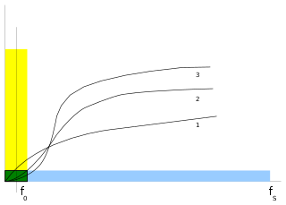
I am aware that a general sigma-delta noise shaping architecture has a noise shaping characteristic of a differentiator as shown below:

enter image description here

1,2 and 3 indicate the orders of noise shaping and sigma delta architectures too.

For example, if we consider the following continuous-time sigma-delta architecture (first order), the noise shaping is governed by the equation: enter image description here NTF(z)=(1-z^(-1)), which translates to the curve (1) of the first figure.
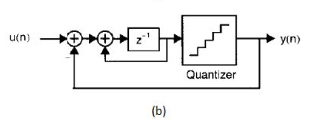
Simulation background for IDSM:

When I simulate an incremental sigma delta converter (IDSM), I run it for (N*(1/fs)*OSR), where it runs for OSR clock cyles for single conversion. I run the output through the counter and then scale it by (1/M) for every reset (Decimation) and then view the spectrum with N points, I am able to get the desired output SNR for an IDSM.

One conversion cycle is shown below (M=OSR).

enter image description here

Core question:

I designed a continuous-time first-order sigma delta modulator in matlab and the output spectrum is shown below: enter image description here
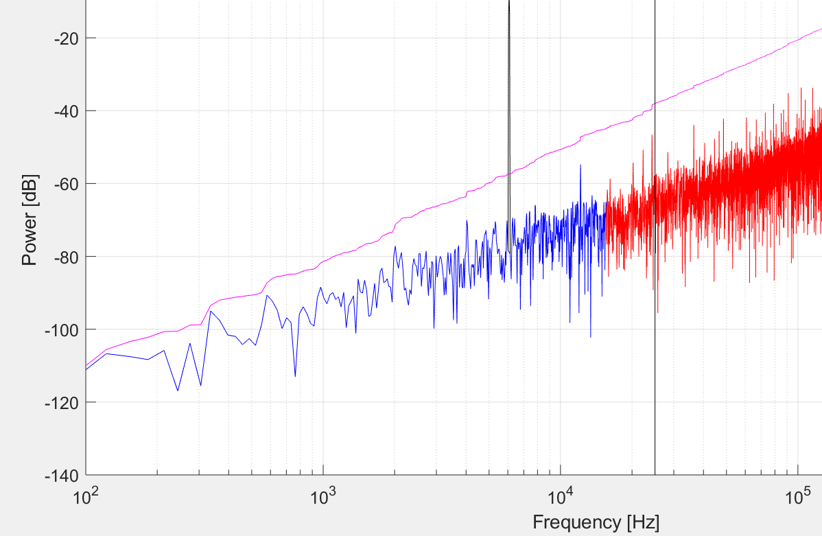
Here I am able to see the first order noise shaping (-20dB/decade noise increment).

Now, how do I simulate the output from an IDSM to view the result of noise shaping?.

I saw some articles, plotting noise shaped spectrum for IDSM (in free running DSM mode). I am really not sure how to run an IDSM in this mode, because logically it would require a reset for each conversion and therefore I am stuck.

(Again, I could decimate the output of IDSM and then view the spectrum - which gives me the correct SNR. But I'm interested in viewing the noise shaping behavior.)

If what i am expecting is not achievable, please let me know as well - that would be helpful too.

$\endgroup$
4
  • 1
    $\begingroup$ I have estimated the noise shaping using loop equation transfer functions, which is good to functionally further understand how noise shaping occurs for first and higher order loops, but the issue is the transfer equations assume a linear model and the quantizer makes this extremely non linear (consider the equivalent linear gain of the quantizer for different signal levels-- it is completely level dependent and the loop models are in the frequency domain not the amplitude domain. That said, if info on this approach will still help you I can provide further details as an answer. $\endgroup$ Commented May 1, 2020 at 12:33
  • $\begingroup$ @DanBoschen Firstly thank you for the comment and the Answer. Well, the noise transfer function that you just described is for generic sigma delta loop. However, I was looking for a noise shaped spectra of the incremental sigma-delta loop output - which I realized after working on it, cannot be plotted (only flitered output can be plotted) when we run it in incremental mode because of the periodic reset.. The noise shaping characteristic has to be tested only in the free running mode or the noise transfer function can be plotted as u just described. $\endgroup$
    – sundar
    Commented May 2, 2020 at 6:16
  • $\begingroup$ So, anyway to close this question by "not achievable" or "not possible"? $\endgroup$
    – sundar
    Commented May 2, 2020 at 6:20
  • $\begingroup$ Ah i see! I was not familiar with the “incremental sigma delta” but now see what you are referring to. I may delete my answer but to think through first wouldn’t it still apply? From reset to result this is what would still occur almost like comparing an integrate and dump to a moving average (?) $\endgroup$ Commented May 2, 2020 at 11:00

1 Answer 1

1
$\begingroup$

Update: as Sundar commented his question is specific to the “incremental Sigma Delta ADC” of which I only have a vague understanding of. To the extent the incremental implementation is a traditional Sigma Delta ADC that is reset periodically I would believe this model still applies as described similar to using a moving average frequency response to model an integrate and dump. Comments welcome.


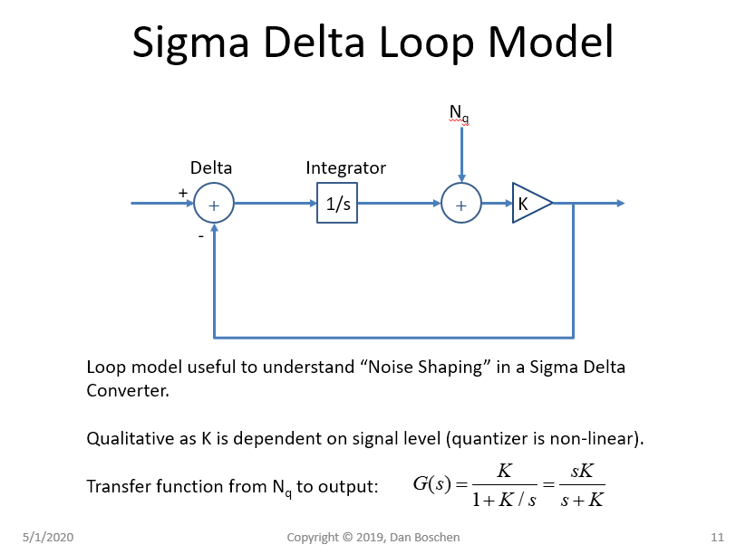
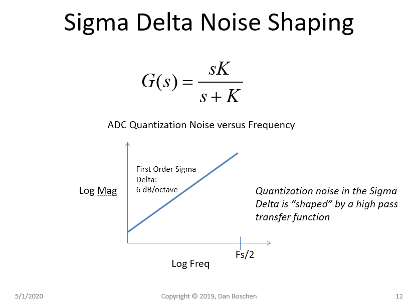
Below is how I use an equivalent loop equation to model the noise shaping in first and higher order Sigma Delta architectures. This is qualitative since the quantizer is highly non-linear (So would a apply from a small signal perspective, and can be further more accurately approximated with a piece-wise linear approximation to the quantizer gain.

Below shows continuous time equivalents, with $N_q$ as the quantization noise input from the 1 bit converter. The discrete time equivalent is easily derived by mapping the integrator. An integrator using either Backward Euler or Impulse Invariance mappings both result in:

$$\frac{1}{s} \leftrightarrow \frac{T}{1-z^{-1}}$$

Sigma Delta Loop Model

Loop Equation

$\endgroup$

Your Answer

By clicking “Post Your Answer”, you agree to our terms of service and acknowledge you have read our privacy policy.

Not the answer you're looking for? Browse other questions tagged or ask your own question.