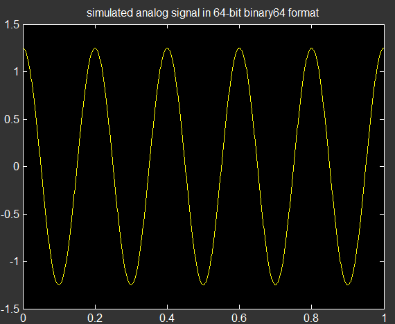
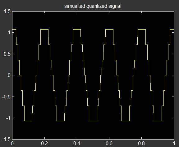
ADCs are devices which can be simplified to behave ideally but are actually not doing so due to their physical limitations. Hence if you would like to make a realistic simulation of ADCs, then you should seriously consider their physical charactheristics as well. Otherwise if you are ok with the ideal mathematical definition of their outputs then the following simple MATLAB/OCTAVE code implements an example uniform quantizer. Please be very careful with the concept of simulation when it comes to ADC and quantizers.
clc; clear all; close all;

% ANALOG SIGNAL:
T = 1;          % observaton interval in seconds
f0 = 5;         % input sine frequency in Hz.
Fs = 1000;      % sampling frequency in Hz.

t = 0:1/Fs:T;   % sampling instants time

A = 1.25;       % amplitude of the input sine wave.
ax = A*cos(2*pi*f0*t)-(1E-15);   % ideal analog signal simulated with 64 bit IEEE floating point format
ax(ax <= -A) = -A + 1E-14;       % slight conditioning on the input so that decision limits are maintained.

figure,plot(t,ax);
title('simulated analog signal in 64-bit binary64 format');

% ADC :
N = 3;          % number of bits of uniform, symmetric, midtreat quantizer.
M = 2^N-1;      % number of levels: odd
qx = (2*A/M) *  round( (M/(2*A)) * ax ) ;   % QUANTIZED... (simulated within 64 bit container format)

figure,plot(t,qx),
title('simualted quantized signal');
The input and output are as follows:


