2
$\begingroup$

I want a complex FIR or IIR filter whose response is approximately a sawtooth in the frequency domain. How should this be formally described, and what formula or algorithm can I use to calculate taps for one?

Here is a sketch of the magnitude response I want (not analysis of an actual filter). I think the phase response doesn't matter.

$\endgroup$
9
  • $\begingroup$ Note that since gain is not symmetric around f=0, the resulting filter will be complex, not real. $\endgroup$
    – Juancho
    Commented Jan 1, 2016 at 5:54
  • $\begingroup$ You sketched the magnitude response. Does the phase response matter? $\endgroup$
    – Matt L.
    Commented Jan 1, 2016 at 8:16
  • 2
    $\begingroup$ What you have is basically the frequency response of an approximation to a differentiator (as in d/dt, not d/df). Standard +6dB/octave HP. $\endgroup$ Commented Jan 1, 2016 at 22:29
  • 1
    $\begingroup$ Ollie: I didn't bother including the $j$ in front of my $h[k]$ terms. Our answers are the same except I failed to account for the non-zero freq-domain magnitude at zero Hz as you did. Good job Ollie. Adding a constant to the center sample of a symmetrical impulse response has interesting properties, does it not? For example, if you negate a lowpass filter's symmetrical coefficients and add one to the center coefficient you produce a highpass filter. (In any case, this was an interesting thread.) $\endgroup$ Commented Jan 2, 2016 at 5:06
  • 1
    $\begingroup$ Kevin: For some reason you mentioned taps "in reverse order". I'm not sure what you had in mind but I'll mention that the imaginary parts of Ollie's and my $h[k]$ values are the negative of Oppenheimer & Schafer's digital differentiator's $h[n]$ on page 483 of their 2nd Edition. So the imaginary parts of Ollie's and my $h[k]$ values are reversed in order compared to a standard differentiator's real-valued $h[n]$ coefficients. $\endgroup$ Commented Jan 2, 2016 at 5:07

5 Answers 5

3
$\begingroup$

A windowed design is easy. Starting with an ideal zero-phase frequency response:

$$\frac{\omega}{2\pi} + \frac{1}{2}$$

The inverse Fourier transform of that gives the ideal impulse response:

$$\int^\pi_{-\pi}\left(\frac{\omega}{2\pi}+\frac{1}{2}\right)e^{i\omega k}d\omega = \frac{\sin(\pi k)}{k} + i\left(\frac{\sin(\pi k)}{\pi k^2} - \frac{\cos(\pi k)}{k}\right).$$

Similar to the $\text{sinc}$ function, the real part $\frac{\sin(\pi k)}{k}$ has an illegal division by zero at $k=0$ where the limiting value $\pi$ should be used instead. For other integer $k$, the real part is zero. The imaginary part has similar problems at $k=0$, where its limit is 0. Drawing from Rick's answer, at integer $k$, $\sin(\pi k)$ is zero and $\cos(\pi k)$ is +1 or -1. This simplifies the ideal impulse response at integer $k$ to:

$$\begin{cases}\pi&\text{if }k=0, \\i\frac{-(-1)^k}{k}&\text{otherwise.}\end{cases}$$

If the filter is implemented as a sum of a purely real and a purely imaginary filter, the purely real filter requires no work other than to multiply the input by a constant. The imaginary part of the impulse response is antisymmetrical, which may enable savings.

To continue with the windowed design, choose a window function and its length (equals the number of filter taps) and multiply the ideal impulse response by it. That gives the impulse response of the filter. The window function should be centered at $k = 0$.

$\endgroup$
2
  • 1
    $\begingroup$ It's maybe worth pointing out that strictly speaking the formula for $h[k]$ is only valid for $k\neq 0$. The value for $k=0$ is purely real-valued. $\endgroup$
    – Matt L.
    Commented Jan 1, 2016 at 20:44
  • $\begingroup$ I've found this to work well and be simple to implement. Here is my implementation (for GNU Radio). · I agree with Matt L. that some words in the answer mentioning that the limit should be taken to define it at 0 would be good. · Also, I did not find the filter taps to be “in reverse order”; perhaps this is just a difference in sign/direction conventions. $\endgroup$
    – Kevin Reid
    Commented Jan 2, 2016 at 0:23
2
$\begingroup$

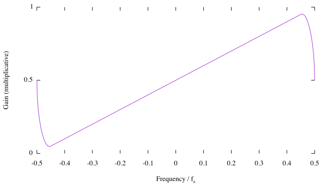
For general filter designs, a least squares method is usually a good start. The window method suggested by Olli Niemitalo is also useful, but it is a bit less flexible because you can't define "don't care regions" (which is important for dealing with discontinuities in the desired response). Furthermore, with least squares you can add a weighting function which marks certain frequency regions as more important than others, resulting in a smaller approximation error in those regions. And finally, with least squares you don't need to analytically compute an inverse DTFT, which is not always possible in practice.

A simple Matlab/Octave script for a least squares design (without weighting) looks like this (note that I assume a linear desired phase response):

N = 101;                                 % choose some filter length
w = 2*pi*linspace(-.45,.45,200);         % frequency grid with don't care regions
d = (.5+w/(2*pi)).*exp(-1i*w*(N-1)/2);   % desired response (linear phase)
A = exp(-1i*w(:)*(0:N-1));               % matrix of overdetermined system A*h=d
h = A\d(:);                              % least squares solution
% plot designed frequency response
wp = linspace(-pi,pi,512);
H = freqz(h,1,wp);
plot(wp/2/pi, abs(H)); axis([-.5,.5,0,1])

enter image description here

$\endgroup$
2
  • $\begingroup$ In this case, I don't really have an identifiable don't-care region, and so I'm going to go with the window method as described in Olli Niemitalo's answer, but thank you for illustrating another technique. $\endgroup$
    – Kevin Reid
    Commented Jan 1, 2016 at 23:09
  • $\begingroup$ @KevinReid: That's OK. Just FYI: you usually don't have a don't care region, but you define one in order to get a better approximation to your idealized response. I defined don't care regions close to $\pm 0.5$ (in the plot) because there are the discontinuities that are difficult to approximate. This results in a smooth approximation without overshoot. $\endgroup$
    – Matt L.
    Commented Jan 2, 2016 at 8:53
1
$\begingroup$

What you have is basically the magnitude response of a sampled differentiator.

$y(t|t=nT) = \frac {d}{dt} x(t)$

This is a basic first order high pass filter with a +6dB/octave slope.

The simplest possible approximation would be a one zero filter.

$y[n] = a_0 * (x[n] - x[n-1])$

You could add a pole to that for a better low frequency match, or you could go all in with a windowed FIR design like Olli Niemitalo (what is the markdown syntax for proper @-attribution?) mentioned above.

https://ccrma.stanford.edu/~jos/fp/One_Zero.html

$\endgroup$
2
  • 1
    $\begingroup$ If you want to refer to another answer, link to it. @s are just for notifying people in comments/chat and are not special other than that (they don't even update if the username changes). $\endgroup$
    – Kevin Reid
    Commented Jan 2, 2016 at 15:06
  • 1
    $\begingroup$ The filter is related to a differentiator but it's actually a complex-valued filter due to the lack of frequency domain symmetry. Note that at $\omega=0$ the desired frequency response is not zero, as it should be for a differentiator. $\endgroup$
    – Matt L.
    Commented Jan 3, 2016 at 13:09
0
$\begingroup$

Figuring out the Fourier series for a sawtooth wave in the time domain is a common exercise. That same series will be the time domain impulse response for a sawtooth in the frequency domain. Since you want odd symmetry, all imaginary (but conjugate symmetric if you want a real result).

$\endgroup$
-1
$\begingroup$

I plugged a frequency response of $\omega$ into the inverse discrete-time Fourier transform (inverse DTFT) equation and ended up with:

$$h[k] = \frac{\sin(k\omega_c)}{k^2\pi}-\frac{(\omega_c)\cos(k\omega_c)}{k\pi}$$

where $\omega_c$ is the cutoff freq measured in radians. Index $k$ is ...-3,-2,-1,0,1,2,3.... When $k = 0$ set $h[0] = 0$. (You may want to multiply $h[k]$ by a window sequence to reduce the frequency magnitude response ripples.) If we set $\omega_c = \pi$ we end up with:

$$h[k] = \frac{-(-1)^k}{k}$$

Try out the above $h[k]$'s. Who knows, they might work for you. (The $h[k]$ equations are supplied "as is." No warranty of any kind, either expressed or implied.)

$\endgroup$
3
  • 1
    $\begingroup$ Richard, there must be something wrong here: the resulting impulse response must be complex-valued because the desired frequency response is not conjugate symmetrical. [Anti-paranoia disclaimer: I'm not targeting you, I just happened to see this pretty quickly because I just provided an answer myself ...] $\endgroup$
    – Matt L.
    Commented Jan 1, 2016 at 12:36
  • $\begingroup$ Matt L.: You can put a $j$ operator in front of my two $h[k]$ expressions if you wish, but that doesn't change their freq magnitude responses. [Why the paranoia comment? Matt L. please be civil, OK?] $\endgroup$ Commented Jan 1, 2016 at 18:59
  • $\begingroup$ The desired response lacks the required symmetry, so a $j$ in front is not sufficient: $h[n]$ must be complex-valued, with non-zero real part and non-zero imaginary part (see Ollie's answer). The other comment referred to your previous comment elsewhere accusing me - for whatever reason - of always trying to find errors in your answers, which is of course not the case; so I've tried to be a bit more careful with you, again wrong ... $\endgroup$
    – Matt L.
    Commented Jan 1, 2016 at 19:13

Your Answer

By clicking “Post Your Answer”, you agree to our terms of service and acknowledge you have read our privacy policy.

Not the answer you're looking for? Browse other questions tagged or ask your own question.