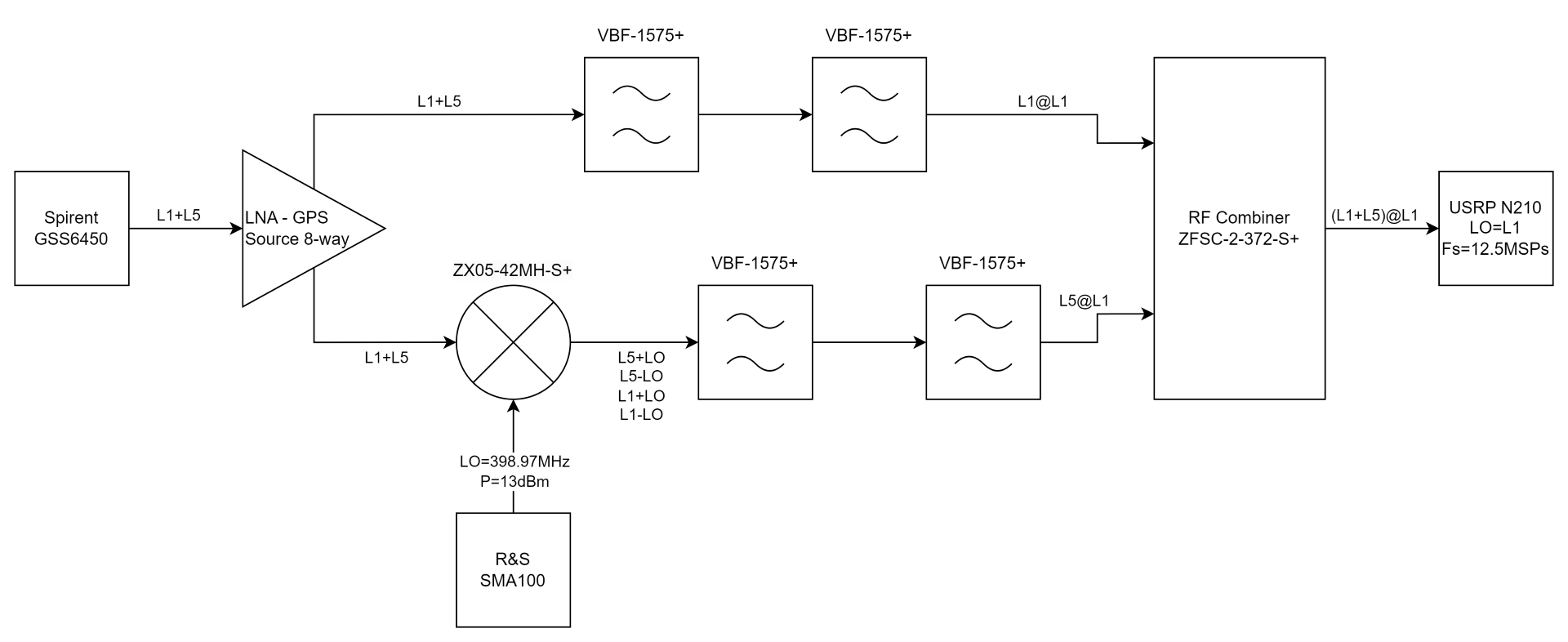
I want to record GPS signals from the L1 (1575.42MHz) and L5 (1176.45MHz) using the USRP N210. The USRP N210 has the UBX 40 USRP Daughterboard which has a bandwidth of 40MHz, meaning I need to shift either the L1 to L5 or L5 to L1 frequency. I shifted the L5 signal to the L1 frequency (L5@L1). The source of our GPS signal is a record and replay system (Spirent GSS6450) connected to an active LNA splitter (GPSS Source 8-way). Only two of the splitter’s outputs are being used. The first goes to a branch where the L1 is selected using two bandpass filters (VBF-1575+) and then connected to an RF combiner (ZFSC-2-372-S+). The other branch does the up-conversion of the L5 to L1 (L5@L1). The signal from the splitter goes to an RF mixer (ZX05-42MH-S+) with a LO of 398.97MHz (L1-L5) generated with SMA100 with a power of 13dBm. Then using two VBF-1575+ the L5+LO (L5@L1) is selected and it goes to the combiner so that at the input of USRP N210 I get both the L1 and L5 signals at the L1 frequency ((L1+L5)@L1). Then the USRP N210 brings the signal to the baseband (LO=L1) and samples it at 12.5MHz, where the IQ samples are stored in a binary file. To validate the approach, I am using the recorded file in "gnss-sdr" open-source library and trying to get positioning. Although both signals (L1 and L5 signals) are being acquired, the tracking does lose lock to the signals before aligning with them, which leads us to assume that there may be something wrong with our approach. Does anyone have tried this before? Is something wrong with our approach?

1 Answer
As drawn the L5 path will have about 7 dB more loss than the L1 path, in addition to a 3 dB Noise Figure penalty if there is no filter for image rejection between the LNA and mixer, thus would have a C/N penalty of about 10 dB plus the noise figure of the LNA versus being connected directly (is this consistent with what you see?).
The 3 dB penalty is because of the amplified noise floor in the image frequency location (which is the sum frequency at 1575.42 MHz + 398.97 MHz: any noise in this frequency band will also translate to the output at 1575.42 from the double side-band frequency translation of the mixer). A low loss image rejection filter that lowers the amplified noise floor at 1.97 GHz to be even just 15 dB lower than the amplified noise floor at 1176.45 MHz (as presented to the input of the mixer) will avoid this noise figure penalty. Such filtering may already be provide in the LNA-GPS 8-way source and can be measured for verification.
If such filtering is added, the issue of the gain mismatch still exists which desensitizes the L5 path. This can be compensated with additional gain such that the amplified noise at the two inputs to the power combiner are adjusted to ideally be the same. This would result in a minimum noise figure penalty for each band of 3 dB plus the ohmic loss of the power combiner (0.5 to 1 dB expected) plus the noise figure of the front-end LNA (so perhaps 5 dB total C/N degradation). Depending on the application, a 5 dB noise figure penalty overall may be acceptable. This is better than the 13+ dB hit on the L5 path as now configured, and I can't think of a way to improve this further without great complexity (further improvement that I can conceive would require and intermediate combining stage with offsetting the L5 and L1 bands by about 6.25 MHz combined with filtering of each to isolate their noise floors from combining).
-
$\begingroup$ Thank you for the detailed reply. Accounting for what you mentioned and the components I have available I made the switch to bring the L1 to the L5 band and record in the L5 band. In this way, I could add the VFB-1575+ filter before the mixer. In the new circuit I managed to get positioning with gnss-sdr using the L1@L5 and L5@L5. The extra L1@L1 that reaches the UBX daughter board is filtered out by it, meaning only (L1+L5)@L5 reach the ADCs $\endgroup$ Commented Oct 8 at 15:56
-
$\begingroup$ Good plan. Are you able to balance the gains to the Power Divider input? Adding an attenuator on the direct path leg should do it (reducing how much it would otherwise desensitize the lower power leg). The assumption here is that you have at least 15 dB of gain in your LNA to overcome the mixer loss. $\endgroup$ Commented Oct 8 at 16:49
