16
$\begingroup$

I thought that DSP would be done by using FFT of portions of a signal, modify the samples that result from FFT (since they represent the spectrum of our signal + noise) and remove any unwanted signals and than do an inverse FFT to get a time domain representation of the filtered signal (noise has been removed now). This however is not done, instead we do all the work in time domain using window functions. Why?

If we multiply window function in time domain than we are convolving the window function's frequency response with spectrum of our signal in frequency domain, how does that work out? I mean if we just did all the work in frequency domain by multiplying our signal with the frequency response of the filter, that would be like filtering right? But here we do all the stuff in time domain instead using window.

->Lets see where my confusion comes from. For analogue filters e.g low pass filter, we have this pulse like frequency response. When we filter a signal, we are effectively multiplying our signal's spectrum with the pulse like frequency response of the filter. This will reduce all frequencies in our signal above a cut-off to 0. This is how a low pass filter works in essence. Why not do the same with digital filters as well?

$\endgroup$
1

9 Answers 9

11
$\begingroup$

Windowing reduces spectral leakage.

Say you start out with a $\sin(y) = \cos(\omega_0 t)$. The period is obviously $2 \pi/ \omega_0$.

But if nobody told you that the period is $2 \pi/ \omega$ and you blindly choose the range $[0, 1.8 \pi/\omega_0]$ and take FFT of this truncated waveform, you will observe frequency components in other frequencies which are all fake because the jumps created by copy-pasting the truncated waveform for periodicity are not really present in the original signal - it is an artifact of an unlucky truncation that does not capture the transition between periods smoothly. Ideally there is only one spectral component at $\omega = \omega_0$.

The purpose of windowing in time domain is to reduce all these fictitious spectral components.

$\endgroup$
15
$\begingroup$

Windowing is used because the DFT calculations operate on the infinite periodic extension of the input signal. Since many actual signals are either not periodic at all, or are sampled over an interval different from their actual period, this can produce false frequency components at the artificial 'edge' between repeated intervals, called leakage. By first multiplying the time-domain signal by a windowing function which goes to zero at both ends, you create a smooth transition between repeated intervals in the infinite periodic extension, thus mitigating the creation of these artificial frequency components when we then take the DFT.

This paper gives a more in depth look at this phenomenon, as well as some insight into the effects of different windowing functions.

$\endgroup$
2
13
$\begingroup$

There have been several good answers to this question. However, I feel that one important point has not been made entirely clear. One part of the question was why we don't just multiply the FFT of a signal with the desired filter response. E.g., if we want to lowpass filter our signal, we could simply zero all frequency components higher than the desired cut-off frequency. This is in fact a simple application of the well-known frequency sampling method for designing FIR filters. The problem is that we can just zero the discrete frequency components computed by the FFT. We have no control over what happens in between these discrete frequencies. It turns out that such a simple version of filtering will only give a poor stopband attenuation (regardless of the FFT length). If you have access to matlab or octave, it's very instructive to try it yourself:

x=2*rand(1024,1)-1;
X=fft(x);
Y=X.*[ones(200,1);zeros(625,1);ones(199,1)]; % lowpass filter
y=real(ifft(Y)); % real() just to remove numerical errors
Y=fft(y,4096);
plot(20*log10(abs(Y(1:2048)))),axis([0,2048,-30,50])
$\endgroup$
12
$\begingroup$

I think you are confusing two different operations.

Windowing in the time domain is explained by @sam, so I won't repeat that. But windowing is not done to perform filtering. Filtering by multiplying the FFT of a signal by the filter frequency response is entirely reasonable in many situations, and is indeed done. The alternative for filtering is time-domain convolution (which is different to windowing). This has its own advantages, such as operating on a signal in 'real-time' as it is measured without waiting for the whole thing to be stored then transforming.

So to your question 'Why not do the same with digital filters as well?', the answer is simply 'we do, when it suits.'

$\endgroup$
1
  • 1
    $\begingroup$ I also have the impression, that convolution and windowing got mixed up in the question. Good you pointed it out! $\endgroup$
    – Deve
    Commented Oct 26, 2015 at 12:58
6
$\begingroup$

If you don't use a non-rectangular window, then the FFT results will already be convolved with the transform of a default rectangular window (a periodic Sinc) before doing any frequency domain filtering. e.g. you will get two filters applied, one of which you probably don't want.

By windowing in the time domain, before the FFT and frequency domain filtering, you replace any filtering (so-called "leakage") done by rectangular windowing, and thus don't get an additional unwanted filter convolution.

The other way to do this is to use overlap-add or overlap save methods on consecutive windows, where the effects of one rectangular window get cancelled by similar effects from the adjacent windows.

$\endgroup$
5
$\begingroup$

Window in the time domain because

  • we can guarantee zero at the edges of the window
  • window functions have a nice analytic expression in spatial domain
  • many window functions have a weird shaped spectrum that would be hard to approximate
  • only a finite number of samples are needed (windowing can be done as the signal streams in)

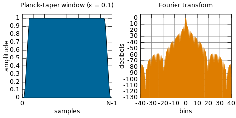
e.g. from wikipedia

enter image description here

The hard cut off going to zero of windowing functions means in the spectral domain they have side lobes that go to zero very slowly. If we get rid of this constraint we can have functions that are compact in both spatial and spectral domains, like the Gaussian filter. This means you could filter via the spectral domain but that requires the whole signal to be known.

If you do have the entire signal already another alternative would be to use wavelets

$\endgroup$
2
$\begingroup$

I had the same question.

A convolution is the integral/cumulative sum of the time domain signal multiplied with the window. This should not be confused with the "windowed" time domain signal.

The end of this article helped me a lot.

Basically it says that real signals are finite and abruptly cutting off a real signal results in lots of unwanted frequencies/artifacts in the frequency domain.

In order to avoid/minimize these artifacts you can use a smooth (eg. bell shaped) window function such that your sample starts and ends with a zero, rather than abruptly ending with some non zero scalar value.

Smooth cut off

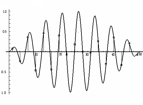
The windowed sample above will have less artifacts in the frequency domain than the raw sample below.

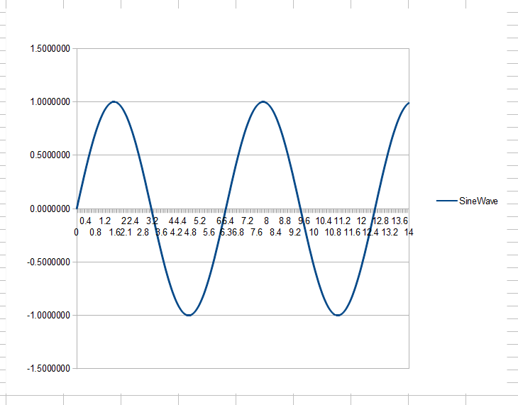
Abrupt cut off

$\endgroup$
2
$\begingroup$

Windowing in the time domain is required to avoid a single frequency that is not exactly on a frequency bin to spread out over the entire spectrum. Maybe this page helps: http://www.sm5bsz.com/slfft/slfft.htm Linrad (my 20 year old project) uses a windowed FFT, then applies a filter in the frequency domain (make zero what we do not want.) Apply a window - do not go abruptly from weigtht 1 to weight 0 on the frequency bins. Then apply a backwards FFT - but now on a much smaller number of points. There is no need to include all the frequency bins we know are zero!! As a resulr we get a time function with a much smaller size - that means with a much lower sampling rate. The procedure does filtering and decimation in a single step. This is very efficient in case one wants to filter out several channels at the same time. The linrad home page is here: http://www.sm5bsz.com/linuxdsp/linrad.htm

$\endgroup$
1
$\begingroup$

There are two broad categories associated with an FFT and they are 1) an efficient way to implement an FIR filter, and 2) Spectral Analysis.

For FIR Filtering, one does not worry about windows and does not use them, unless the window corresponds to a filter, but that isn't a common thing to do. Leakage is not a concern.

Spectral Analysis is where one uses windows. This is where you look at a sensor attached to a big industrial machine and try to figure out if deep in its bowels, a bearing failing. Bearings squeal as they fail but the noise they may is usually much lower than the other sounds the machine is making. This is where leakage and averaging comes in. Given strong tones, leakage will swamp out the weak signal we are looking for a few bins over. It improves the sensitivity of Spectral Analysis to weak signals in the presence of strong signals. There is a similar effect when the background noise is sloped. The information we seek is in the frequency domain. This is the same problem in RADAR, and SONAR, and Geophysics. Seeing the weak signal is goal.

$\endgroup$

Your Answer

By clicking “Post Your Answer”, you agree to our terms of service and acknowledge you have read our privacy policy.

Not the answer you're looking for? Browse other questions tagged or ask your own question.