1
$\begingroup$

I am trying to implement an SDR transmitter and receiver based on the description here.

def sdr_transmitter(signal: np.ndarray, frequency: float, sample_period: float):
    """
    Encode input signal in the form of IQ values to output signal.
    """

    Is = signal[:, 0]
    Qs = signal[:, 1]

    t = np.arange(0, signal.shape[0] * sample_period, sample_period)

    in_phase = Is * np.cos(2 * math.pi * frequency * t)
    quadrature = Qs * np.sin(2 * math.pi * frequency * t)

    signal = in_phase + quadrature

    return signal

def sdr_receiver(signal: np.ndarray, frequency: float, sample_period: float):
    """
    Takes the signal and extracts the in-phase and quadrature components.
    In other words, extracts the cosine and sine components, the I and Q.
    """
    t = np.arange(0, signal.shape[0] * sample_period, sample_period)

    cos_wave = np.cos(2 * math.pi * frequency * t)
    sin_wave = np.sin(2 * math.pi * frequency * t)

    Is = signal * cos_wave
    Qs = signal * sin_wave

    output = np.stack([Is, Qs], axis=-1)

    return output

and I test it like this:

sample_period = 0.02
Is = np.full(100, fill_value=1)
Qs = np.full(100, fill_value=1)
signal = np.stack([Is, Qs], axis=-1)

output = sdr_transmitter(signal, frequency=2, sample_period=sample_period)
signal_output = sdr_receiver(output, frequency=2, sample_period=sample_period)

where the signal and signal_output should equal. However, they do not. Since the Is and Qs are constant, I should get the same constant values after demodulation by the receiver. I believe that by multiplying by sin and cos waves, I should get those values thanks to the Frequency Shift Property (from here): $$e^{2 \pi j f_0 t}x(t) \leftrightarrow X(f-f_0)$$

Thus, after subtraction of the frequency, the resulting frequency should be zero, which means that only constant values remain, and in fact, the constant values should be equal to the original Is and Qs. What I observed is the opposite; the frequency increased (see the plots below).

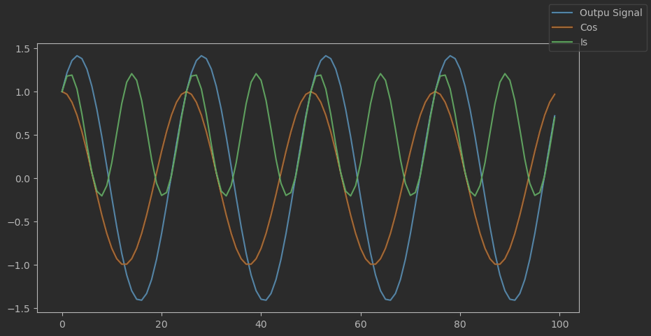
Transmitter: Let's look at the signals inside of the transmitter using the example above. Note that the in-phase signal overlaps with the cosine since the Is are all equal to 1.

The signals inside of a transmitter

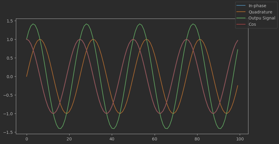
Receiver: Now, let's see what happens when the signal is multiplied by cosine and check whether the Is are what we expect.

enter image description here

We can see that the Is do not represent a constant function at 1, but instead, it is a wave with a higher frequency than the signal or the cosine.

Apparently, I misunderstood something and can't figure out what. Any advice will be appreciated. Thanks a lot!

$\endgroup$
0

1 Answer 1

1
$\begingroup$

The signal given as by signal = in_phase + quadrature is a real passband signal with Is and Qs as a complex baseband signal. (This should actually be signal = in_phase - quadrature to avoid spectrum reversal, only noted as this isn't the OP's primary issue but noted.) For down-conversion, additional low pass filtering is required to remove the high frequency (double frequency) component. In the OP's case, simple averaging (which is a low pass filter) will result in the expected constant function.

Both processes are given from the shift property of the Fourier Transform which states that multiplying a function $x(t)$ in the time domain by $e^{j\omega_c t}$ will shift the frequency by $\omega_c$. If $\omega_c$ is positive the frequency will be translated up, and if $\omega_c$ is negative the frequency will will be translated down:

$$\mathscr{F}\{x(t)e^{j\omega_c t}\} \leftrightarrow X(\omega-\omega_c)$$

The function $e^{j\omega_c t}$ itself is a "spinning phasor" in the time domain, and has a transform as a single impulse in the frequency domain (a single frequency tone, and thus a sinusoid consists of two tones as positive and negative frequency components). Multiplication in time is convolution in frequency, which results in a simple shift. Also multiplying exponentials results in a summation of the exponents which may also provide further mathematical intuition: $e^{j\omega_1 t}e^{j\omega_o t} = e^{j(\omega_1+\omega_o)t}$.

I will use $x(t)$ as the original baseband waveform and $Real\{y(t)\}$ as the real passband waveform:

$$x(t) = I_s+jQ_s$$

$$e^{j\omega_c t} = \cos(\omega_c t) + j\sin(\omega_c t) = I_c+jQ_c$$

$$y(t) = x(t)e^{j\omega_c t} = (I_s+jQ_s)(I_c+jQ_c)$$

$$Real\{y(t)\} = Real\{(I_sI_c-Q_sQ_c) + j(I_cQ_s + I_sQ_c) \}=I_sI_c-Q_sQ_c$$

Thus:

$$Real\{y(t)\} = I_s\cos(\omega_c t) - Q_s\sin(\omega_c t)$$

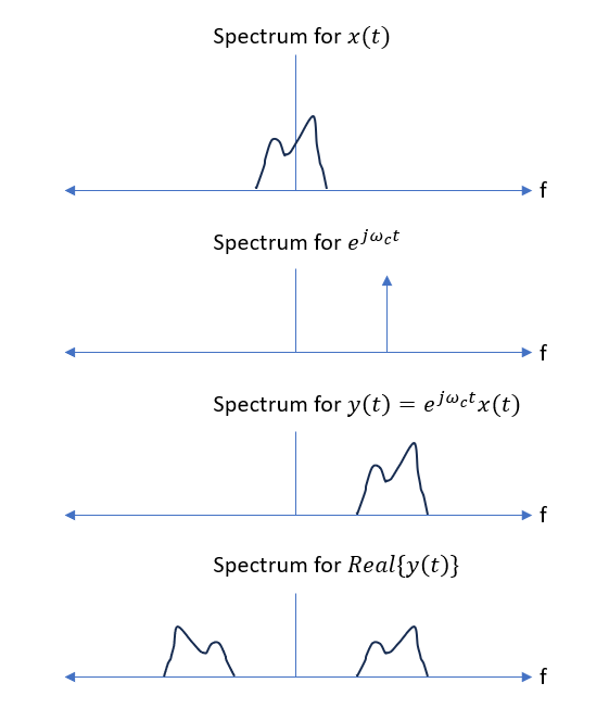
The following graphics below showing upconversion should also help provide further insight and intuition in the frequency translation process:

Upconversion

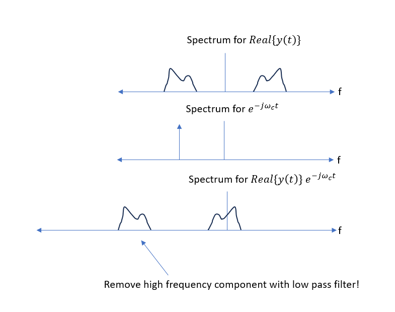
Down-conversion proceeds in reverse by multiplying $y(t)$ by $e^{-j\omega_c t}$ where a high frequency component must be removed by low pass filtering (or use the Hilbert Transform to recreate a one-sided complex passband signal):

down-conversion

Using $y_r(t)$ as the real passband signal, and $x_b(t)$ as the recovered baseband signal, the process is given as:

$$x_b(t) = \text{LPF}\{y_r(t)e^{-j\omega_c t}\}$$

$$x_b(t) = \text{LPF}\{y_r(t)(I_c-jQ_c)\}$$

Thus prior to low pass filtering the recovered complex baseband signal is given as:

$$I_b(t) = y_r(t)\cos(\omega_c(t))$$

$$Q_b(t)= -y_r(t)\sin(\omega_c(t))$$

Alternatively to avoid the need for filtering, the Hilbert Transform can be used to create the Analytic Signal, which converts the real passband into a complex passband with positive frequency components only (which would have the frequency spectrum as depicted in the third row of the first plot). The analytic signal is returned by the hilbert function in MATLAB, Octave and Python’s scipy.signal library. This can then be down-converted by multiplying by $e^{-j\omega t}$.

$\endgroup$
2
  • $\begingroup$ Thank you for this great answer! It sheds light on several perks of signal processing. I did not realize that after the down-conversion I would be left with a high-frequency signal that I need to filter. I would only add that to get the original signal Is being transmitted, one must multiply the filtered down-converted signal by 2. This is because the original signal is decomposed into two parts (with positive and negative frequency), one of which is filtered away. Please correct me if I'm wrong. $\endgroup$ Commented Aug 1, 2023 at 20:28
  • $\begingroup$ I'm glad it helped. You're not wrong but there is no necessity to multiply by 2 specifically. There will be gain in the receiver (likely not "2") to normalize the waveform based on whatever loss the signal has. But your thinking is correct. Half of that signal is filtered away with that approach (and half of the noise as well, so there is no actual loss when we consider SNR) $\endgroup$ Commented Aug 2, 2023 at 5:09

Your Answer

By clicking “Post Your Answer”, you agree to our terms of service and acknowledge you have read our privacy policy.

Not the answer you're looking for? Browse other questions tagged or ask your own question.