7
$\begingroup$

We can use common algorithms such as what is available in firls and firpm in MATLAB for least squares or minimax fitting to target magnitudes at given frequencies. I am familiar with the "Frequency Sampling" method to determine the filter coefficients for an arbitrary magnitude and phase trajectory in frequency. However my understanding is that approach is flawed due to time domain aliasing, which then leads to the question of possible alternative approaches (besides simply oversampling the frequency domain to reduce the time domain aliasing and then using that impulse response with the classic "windowing" method of filtering design - which is a great approach for arbitrary mag / phase responses).

What other approaches are there that can be practically implemented (and do any tools in MATLAB/Octave or Python readily provide this?) for resolving the optimum filter coefficients for that transfer function that will simultaneously meet an arbitrary amplitude and phase response in frequency, in the least squares sense similar to firls? What are the limitations in doing this?

$\endgroup$
9
  • 1
    $\begingroup$ "...an arbitrary magnitude and phase trajectory in frequency"* ----- It's not completely arbitrary if your filter is causal. You can always add delay to make an acausal filter causal (at least for FIR), but adding that delay messes with the phase. $\endgroup$ Commented Apr 16, 2022 at 20:19
  • 3
    $\begingroup$ Frequency sampling with a very large FFT (like a meg or 4 meg or 16 meg) and using double or extended-precision arithmetic can work very well. Apply Kaiser to the resulting impulse response and FFT back to see how good your true frequency response will be. $\endgroup$ Commented Apr 16, 2022 at 20:22
  • $\begingroup$ @robertbristow-johnson I was considering the minimum phase filter is the "given" for any magnitude response, but then we can always add a all-pass to modify the phase----can we get to any phase with the allowance of unlimited complexity (or a least squares solution with a finite number of taps)? Not sure---- but are there conditions of what we could do, and then what would the common techniques be (and ideally are there tools available?) $\endgroup$ Commented Apr 16, 2022 at 20:22
  • 2
    $\begingroup$ @DanBoschen Have you tried this page? $\endgroup$ Commented Apr 17, 2022 at 8:24
  • 1
    $\begingroup$ @DanBoschen FWIW, I've added the answer. But please use @<TAB> because I don't get notified of the reply otherwise (now, I saw this appearing in the hot list so I thought I'd check on it, again). $\endgroup$ Commented Apr 18, 2022 at 12:05

4 Answers 4

4
$\begingroup$

Linear phase FIR filter design is a real-valued approximation problem because only the real-valued amplitude function needs to be approximated. If magnitude and phase are prescribed simultaneously, the resulting approximation problem is complex-valued, because we try to approximate the complex-valued frequency response.

It depends on the chosen optimality criterion whether the complex approximation problem (i.e., prescribed magnitude and phase) is fundamentally more difficult than the real-valued problem (linear phase design). In most cases it is. However, for the least squared error criterion - which I believe is a very practical and useful one - the complex approximation problem is as straightforward to solve as the real approximation problem. Both problems are linear in the filter coefficients (obviously for FIR filters only), and, consequently, the design problem is solved by solving a system of linear equations.

As far as I know there is no function in Matlab/Octave for the least squares design of FIR filters with prescribed magnitude and phase responses, but it just takes a few lines of code to implement it. I wrote the Matlab/Octave function cfirls.m that designs non-linear phase FIR filters with possibly complex-valued coefficients. The function could easily be modified to only allow symmetrical frequency responses to force the resulting filter to be real-valued. Note, however, that even with the function in its current form, the optimal filter for a symmetrical frequency domain specification will be real-valued, up to numerical accuracy.

For other optimality criteria, such as the Chebyshev criterion, the complex approximation problem for non-linear phase filter design becomes more, well, complex. In the linear phase case we have the alternation theorem that is used in the Remez exchange algorithm. In general, nothing similar exists in the complex case. The complex Chebyshev design problem can be approximately solved by solving a linear programming problem. This approach was first proposed by Chen and Parks: Design of FIR filters in the complex domain. This method is very slow compared to the Remez algorithm, but it is nevertheless reliable because methods for solving linear programs are very mature.

It should be noted that when prescribing magnitude and phase responses of a causal filter, we don't need to worry about the Hilbert transform relationship between them, because in practice there are almost always transition bands ("don't care") bands where neither magnitude nor phase responses are specified. Moreover, in stopbands, the phase is unspecified. This gives room for the resulting magnitude and phase responses to match (as Hilbert transform pairs) in any case. Of course, there are limits to what can be achieved with a causal FIR filter, but for a least squares design the result will always be optimal (and unique), even though the resulting filter may not be useful because of a large deviation from the specified response.

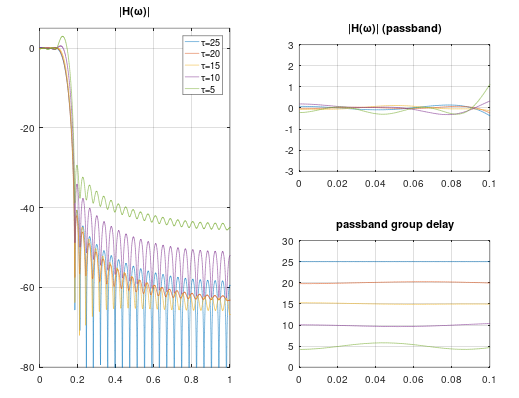
EXAMPLE: Using the function cfirls.m, I designed five $51$-taps lowpass filters with the same magnitude specification but with different desired constant group delays in the passband. In the first case I specified the group delay to be $25$ samples, which corresponds to a linear phase filter. The optimal filter is indeed a symmetrical filter, i.e., a filter with exactly linear phase. The passband group delays of the other four filters were specified to be $20$, $15$, $10$, and $5$ samples respectively. Of course, for very low delays (compared to the filter length), the design goals are harder to meet and the approximation error becomes larger. But for some modest delay reduction the results are still useful. The figure below shows the design results:
enter image description here

$\endgroup$
6
  • $\begingroup$ I was considering the many applications where we aren't using filters to select certain frequencies and block others (which "filter" very much implies!) but more impart a magnitude and frequency relationship across the entire bandwidth. Equalization comes to mind and I am familiar with the Wiener Hopf equations which serves to provide a least squares fit using the input and output waveforms as targets rather than the response--- but then we could use the impulse response itself in the time domain which serves the requirement of being spectrally rich-- how does that approach compare? $\endgroup$ Commented Apr 18, 2022 at 12:03
  • $\begingroup$ (such as I explain in more detail here: dsp.stackexchange.com/questions/31318/… Is this basically your "system of equations to solve the least squares solution" or a different approach you didn't yet list? (As it is using the time domain response rather than the frequency domain, so I though it might be different) $\endgroup$ Commented Apr 18, 2022 at 12:04
  • $\begingroup$ I think the primary difference is to do that we would need to have the impulse response while you are solving the overdetermined set of equations directly in the freq domain but otherwise equivalent-- which then if getting the impulse response is done using DFT it would similar to the "Frequency Sampling" limitation affecting its accuracy, so we end up zero padding and using a much larger DFT to reduce those aliasing effects. Still I'd like to compare the two approaches in more detail if that hasn't already been done; is it something you ever considered? (time domain solution vs freq domain) $\endgroup$ Commented Apr 18, 2022 at 12:10
  • $\begingroup$ I like this answer and wanted to make sure you saw my comments/questions-- wasn't sure if I was supposed to @ you to see it when it's your own response $\endgroup$ Commented Apr 19, 2022 at 3:22
  • 1
    $\begingroup$ @DanBoschen: I think the main difference between the time domain and the frequency domain approaches is that in the frequency domain you could add a weighting function to give more or less emphasis to certain frequency regions. Of course, in the time domain you could weigh different time ranges differently, even though I don't think that this has much practical relevance. $\endgroup$
    – Matt L.
    Commented Apr 19, 2022 at 9:51
3
$\begingroup$

There's an IEEE paper titled: "Designing nonstandard filters with differential evolution" (it might also be a chapter in Lyon's "Streamlining Digital Signal Processing" book), which seems to describe a form of genetic stochastic descent algorithm to fit a pole-zero constellation to an arbitrary frequency response.

$\endgroup$
1
  • $\begingroup$ Thank you hotpaw! @RichardLyons - care to comment, is this covered in your book? $\endgroup$ Commented Apr 17, 2022 at 1:07
3
$\begingroup$

I've implemented two methods that are suitable for "audio" type filters, that are "log/log" in nature. E.g. they have a log frequency axis and/or require high resolution at very low frequencies. This requirement makes FIR designs prohibitively expensive (latency, memory footprint, CPU usage, etc), at least for real time implementations on constrained embedded platforms.

1. Free form IIR filter

  1. Start with set of poles
  2. Calculate the zeros (or residues) in a single step least square error optimization
  3. Iterate poles through a suitable search algorithm (conjugate gradient, steepest descend).
  4. Stop when a suitable termination criteria is met (or you are out of time).

As with most of these things, the are a lot of details to figure out: initial pole selection, iteration step size & method, complex representation, stability constraints, outlier use case handling, stopping criteria, etc. Frequency warping can also help to smooth out the error surface.

This is a confidential (and commercially used) implementation, I'm not aware of anything open source code that does something similar.

2. Warped FIR filters

The basic ideas behind warped FIR filters is to replace the delays of an FIR filter by first order allpass filters. This warps the frequency axis and can be used to make a log spaced frequency grid appear much more linear to fitting algorithms. See for example: https://www.rle.mit.edu/dspg/documents/Proc_Frequency_1999.pdf

  1. Filter designs can be done very similar to normal FIR design by using least squared error methods. You just need to replace the delay transfer functions with the allpass transfer functions.
  2. Each allpass section can have the same corner frequency but it's also possible to use staggered allpass cutoffs.
  3. Optimization of the allpass frequencies typical requires some form of iteration.

Other considerations:

Any random magnitude and phase target will generally not be causal. Trying to fit a causal filter to match a non-causal won't work well. The best way to deal with this, is to add bulk delay to the target (if the application requirements allow it). Determining the "best" amount of bulk delay, can also be part of the iteration process.

Least square optimizers often benefit from tweaking a "weighting" function. For example if a target consists of a +6dB peak and a -6dB dip, a non-weighted LS will put way more work into fitting the peak than the dip.

Many optimizers will require some "out of band behavior" control. For example: if your target is defined from 100Hz to 10kHzat at a 48kHz sample rate, there is non-trivial risk that the gain below 100Hz and above 10kHz becomes way too large. The tricky bit is to add constraints that prevent that from happening without unduly affecting the quality of the fit in the actual target band.

$\endgroup$
1
  • $\begingroup$ Thanks Hilmar! Good insights. $\endgroup$ Commented Apr 17, 2022 at 13:21
2
$\begingroup$

If you think it's worth an answer: on this page there are scripts that deal with transforming measured data into a transfer function and, from there, into some form of implementation.

$\endgroup$

Your Answer

By clicking “Post Your Answer”, you agree to our terms of service and acknowledge you have read our privacy policy.

Not the answer you're looking for? Browse other questions tagged or ask your own question.