2
$\begingroup$

The FFT decomposes a signal into cosine and sine functions, respectively, even and odd components of the signal. Hence, I would expect even symmetric filters to have zero imaginary parts.

Suppose a signal as the following $$x_a[n] = [x_1,\ x_2,\ \textbf{x}_3,\ x_2,\ x_1]$$

This signal is considered symmetric if $\textbf{x}_3$ is considered $t=0$.

However, when applying the FFT, in order to get a representation that has the imaginary component equal to zero, I would first need to shift the signal in order to have $$x_b[n] = [\textbf{x}_3,\ x_2,\ x_1,\ x_1,\ x_2]$$

Would it be correct to say that both $x_a$ and $x_b$ are symmetric?

Filtering a signal by both of these signals would clearly yield two different results.

Am I dealing with two different definitions of symmetric signal?

I understand that all of it is caused by the difference in representation, difference in the location of the point of symmetry. But given the task of filtering an input signal by a symmetric filter, which one should be considered, $x_a$ or $x_b$?


PS: Apologizes if my questions are confusing. I am still trying to better formulate it myself. I am just a bit confused that for linear phase FIR filters it seem to be required to do the ifftshift I mentioned above. I am not sure if this is due to the fact that the symmetric filters are defined in terms of DTFT, and in my application I am working with DFT. So, I would appreciate if someone could put some light into it. Thanks.

$\endgroup$
4
  • $\begingroup$ This rearrangement is equivalent to a cyclic shift. Using numpy, for instance, np.fft.ifftshift([1, 2, 3, 2, 1]) outputs array([3, 2, 1, 1, 2]) $\endgroup$ Commented Jun 17, 2021 at 17:34
  • $\begingroup$ You're right, I was thinking in terms of causality. $\endgroup$ Commented Jun 17, 2021 at 17:35
  • $\begingroup$ What is your purpose? If it is to apply the filter, then $x_a$ is probably what you want because realizable filters (for real-time application) have delay. $\endgroup$
    – Peter K.
    Commented Jun 17, 2021 at 20:55
  • $\begingroup$ I wan't to filter using $x_b$ in the FFT domain. Without the imaginary part of the kernel's representation, my application would run a bit faster. $\endgroup$ Commented Jun 17, 2021 at 21:18

4 Answers 4

3
$\begingroup$
  1. Everything that you can apply an FFT to is discrete in both time and frequency which means it's also periodic in both domains with the FFT length $N$.
  2. Symmetry is clearly defined as $x[-n] = x[n]$ For signals that are periodic with N that extends to $x[-n+2kN] = x[n+2mN]$ where $m$ and $n$ ae integers.

Would it be correct to say that both xa and xb are symmetric?

$x_a$ is not symmetric. It's linear phase but not zero phase.

$x_b$ is symmetric assuming it's periodic with a length of $N=5$ So it's zero phase assuming N = 5

Am I dealing with two different definitions of symmetric signal?

Maybe. Symmetry needs to be properly defined in the context of periodicity.

$\endgroup$
3
$\begingroup$

You really do want to filter using $x_a$.

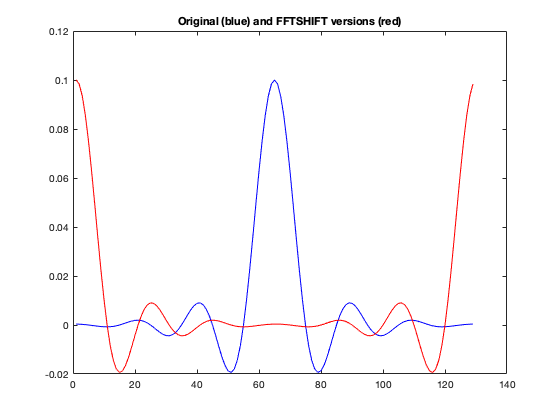
Suppose we design a low-pass FIR filter with the following response.

Original and shifted filter

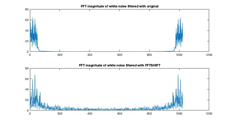
Let's then use them to filter white noise.

Filtered white noise

Notice that the impulse response that has been fftshifted does not yield a good filter output.

The reason is that the filter command uses an FFT length that is $N+M-1$ in length rather than $M$ ($M$ is the impulse response length, $N$ is the data length).

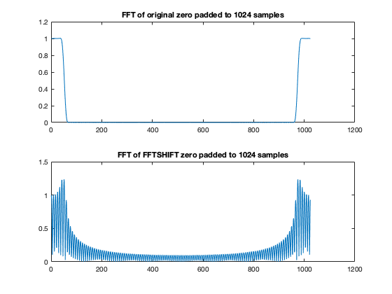
If I take the FFT of each impulse response over a much longer duration, effectively zero-padding the data then I get the magnitude frequency responses shown.

Magnitude frequency responses of the filters over 1024 samples

The original impulse response is still doing the right thing. The fftshifted version is not.


Code Only Below

N = 1024;
x = randn(1,N);

Nf = 128;
h = fir1(Nf,0.1);

h_real = ifftshift(h);

figure(1)
plot(h,'b');
hold on;
plot(h_real,'r');
title('Original (blue) and FFTSHIFT versions (red)');

y = filter(h,1,x);
y_real = filter(h_real,1,x);

figure(2)
subplot(211);
plot(abs(fft(y)));
title('FFT magnitude of white noise filtered with original');
subplot(212);
plot(abs(fft(y_real)));
title('FFT magnitude of white noise filtered with FFTSHIFT');

figure(3)
subplot(211);
plot(abs(fft(h,N)));
title('FFT of original zero padded to 1024 samples');
subplot(212);
plot(abs(fft(h_real,N)));
title('FFT of FFTSHIFT zero padded to 1024 samples');
$\endgroup$
2
$\begingroup$

Symmetric signals are not zero phase. But DFT symmetric are. Not the same.

$\endgroup$
4
  • $\begingroup$ I am a bit confused about Symmetric signals are not zero phase. Linear-Phase Filters have phase either $0$ or $\pi$. And linear-phase filters are also Symmetric (or anti-symmetric). Ref wikipedia. For my application, so far, symmetrical signals seems to always be associated with DFT symmetric. Not in a direct correspondence, but one being the cyclic shift of the other as I mentioned on the question. I am still unsure on which one is to be referred as symmetric. $\endgroup$ Commented Jun 17, 2021 at 21:25
  • 1
    $\begingroup$ Thanks for highlighting that Symmetric Signals are different than DFT symmetric. This might be what I need to accept for my problem. $\endgroup$ Commented Jun 17, 2021 at 21:40
  • $\begingroup$ @EduardoReis Yes, exactly. If it's zero phase, it's DFT symmetric, and such windows are known as "periodic" (e.g. MATLAB see "sflag"). Very simply, DFT symmetric is if x[1:] is symmetric in the standard sense; just drop the first sample. $\endgroup$ Commented Jun 17, 2021 at 21:52
  • $\begingroup$ @EduardoReis And yes you can have zero-phase filters with imaginary component zero in Fourier domain. Take any STFT window that's zero phase and it multiplied by complex sinusoid will be a bandpass filter that's real-only and shifted in FFT domain by frequency of the sinusoid. $\endgroup$ Commented Jun 17, 2021 at 21:55
1
$\begingroup$

This may also help provide an additional intuitive explanation to add to the other good answers posted:

The coefficients of an FIR filter are the impulse response of the filter (a unit sample or "impulse" at the input would result in the coefficients coming out of the filter as we move forward in time). The Fourier Transform of the coefficients (and specifically the Discrete Time Fourier Transform or DTFT) is the frequency response of the filter.

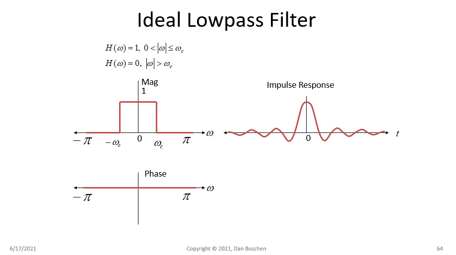
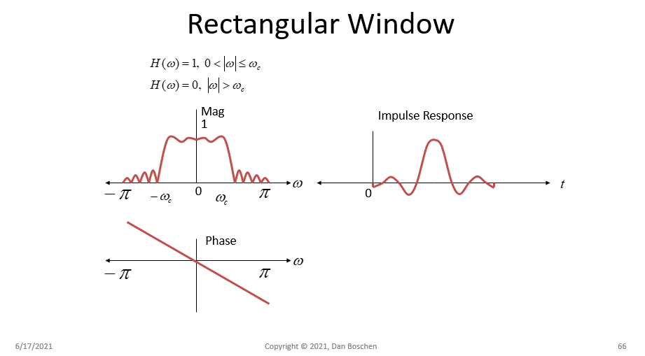
First consider the ideal lowpass filter as a brickwall filter with zero phase. It is ideal as it passes our signal of interest (within the filter bandwidth) with no change to magnitude or phase. This of course is not realizable as evidenced by its Inverse Fourier Transform (the impulse response of the filter needed to realize such a wonderful thing). The impulse response would be a Sinc function in this case that is centered on $t=0$ and extends to $\pm \infty$. We don't have the luxury of infinite time in practice, and given the impulse response has non-zero values before $t=0$ (which is the time that the impulse would appear at the input to cause such a response), the filter in non-causal.

ideal LPF

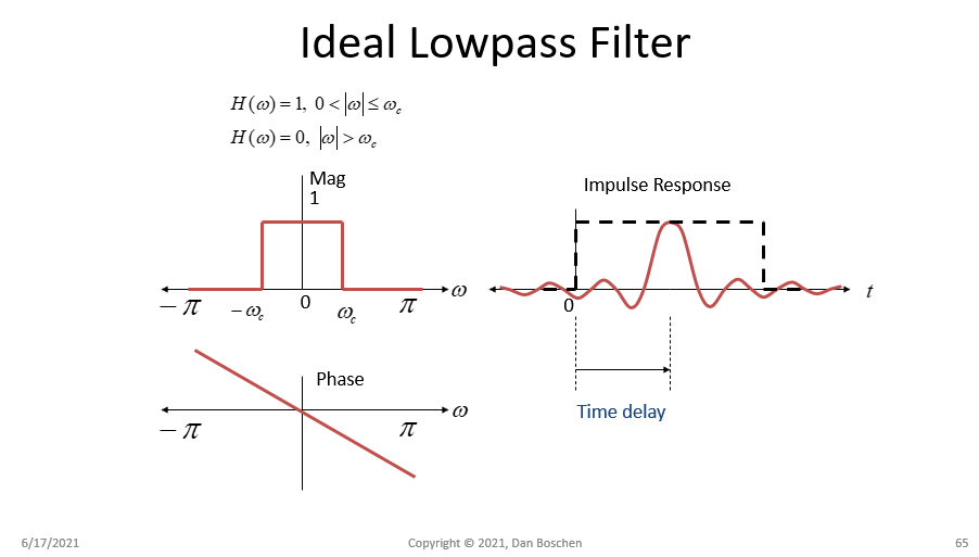
So what is there for us to do? We delay and truncate. The delay alone translates the zero-phase implementation into a linear-phase implementation (the Fourier Transform of a time delay is a linear phase in frequency: $x(t-\tau) \leftrightarrow e^{-j 2\pi f \tau}$)

delay

And the truncation leads to passband and stopband ripple (which we can further improve using windowing):

passband stopband ripple

Thus we see that the coefficients of the FIR filter, which is the impulse response of the filter, are properly represented as a shifted and truncated (and windowed) version of the desired impulse response, and as such properly represents what we can implement in practice, where the output of the filter will be delayed from the input as given by the linear phase slope with frequency.

$\endgroup$
3
  • $\begingroup$ Are we sure sinc isn't realizable? I'm not conclusive but seems this logic applies, difference being sinc is L1 divergent from any tail point to infinity. Might make a Q&A sometime. $\endgroup$ Commented Jun 21, 2021 at 3:43
  • $\begingroup$ Not unless the data is convergent at sufficient rate, I figure. But we'd much sooner run out of data before reaching sinc's float epsilon. If we can acceptably zero the missing data, compute would take ages (10^16 or 10^32 long kernel), and even then we trust so many add-multiplies are accurate. (Yet still, what if convergence in L2 sense is acceptable...) $\endgroup$ Commented Jun 21, 2021 at 3:56
  • $\begingroup$ @OverLordGoldDragon A unit sample is a Sinc sampled at all its zero crossings, but that makes for a poor filter (it is an all pass). But yes, not realizable to the same extent that we also cannot realize in practice brick-wall filters with zero delay. The more delay we can tolerate, the closer we can approximate a brick-wall filter, so equally the more we can approximate a Sinc (with tails below our quantization level of concern). Still you have that delay you have to accept to be causal. $\endgroup$ Commented Jun 21, 2021 at 7:33

Your Answer

By clicking “Post Your Answer”, you agree to our terms of service and acknowledge you have read our privacy policy.

Not the answer you're looking for? Browse other questions tagged or ask your own question.