7
$\begingroup$

I have the task related to Radon transform which contains a subtask which uses resampling by means of DFT.

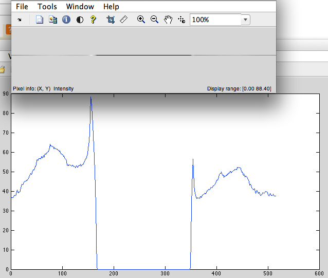
Let's consider the non-periodical discretized signal (Fig.1) (for example the string of pixels) having 515 pixels length. In my implementation for resampling contains following steps:

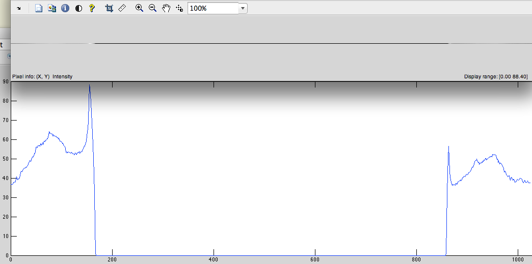
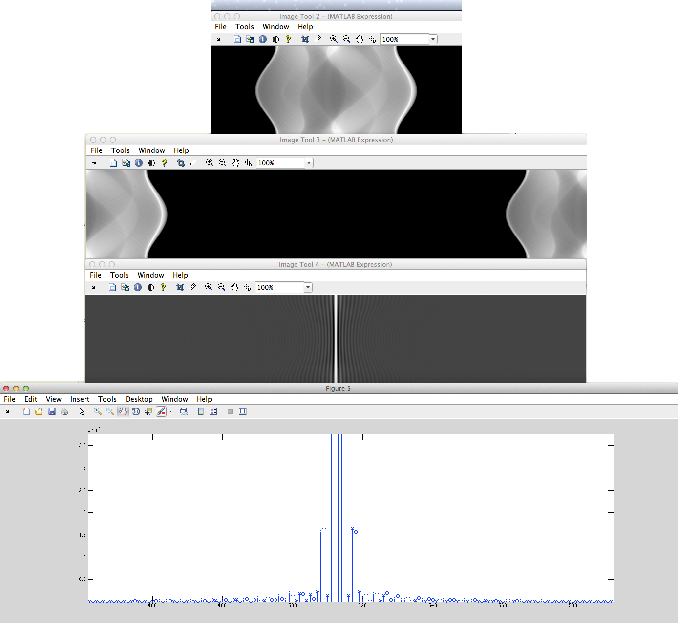
  1. Cyclic left shift (Fig.2).
  2. Add zeros to the center in order to the length of signal became 2^n (in our case 1024-515 = 509 zeros we must have add) (Fig. 3).
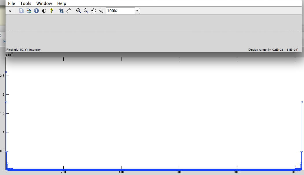
  3. Get DFT from this signal (Fig. 4).
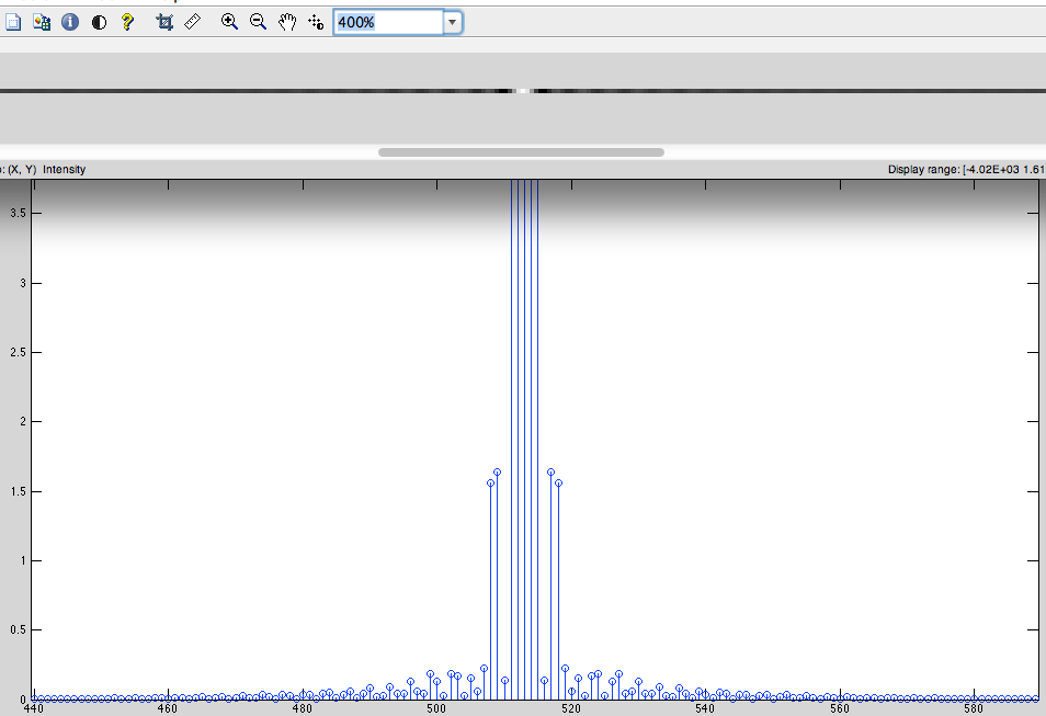
  4. Cyclic right shift. (for shifting low frequencies to the center) (Fig.5)

Fig.1 Original image
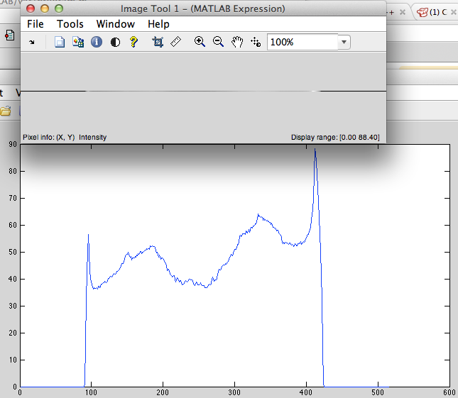
Fig.2 Cyclic left shift

Fig.3 Zeropadded

Fig.4 DFT Spectrum

Fig.5 DFT back shifted

The main question:

Why we must perform cyclic shift of the signal and add zeros exactly in the center? (I assumed what this made the signal periodic) Zeropadding makes interpolation DFT spectrum, is it correct? (I asked and someone says what it is not quite so) Maybe someone can explain in simple way what happens with signal after zeropadding.

I have made some experiments in a Matlab and found out that any other sequence of actions can not give required result.

Now let's consider two cases:

a) (THIS CORRECT VARIANT) We has the non-periodical discretized signal (for example the string of pixels) which will be cyclic shifted to left and filled zeros in the center after that will be obtained DFT from this and to shift it back. enter image description here
b) We has the non-periodical discretized signal (for example the set strings of pixels) which will be filled zeros from left and right after that will be obtained DFT from this.
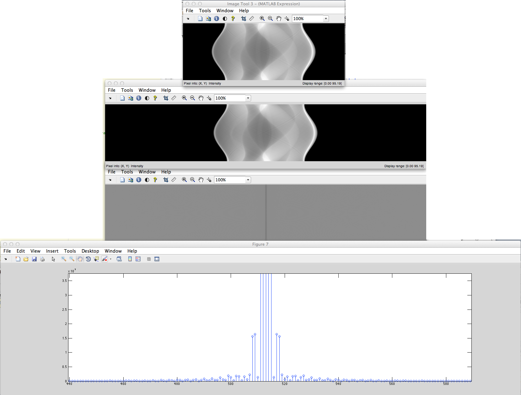
enter image description here

What the difference these DFT spectrums?

I have read some books but not found the answer of this zeropadding's case. It seems this can be found only by own experience.

Answer in book:

A. C. Kak and Malcolm Slaney, Principles of Computerized Tomographic Imaging, Society of Industrial and Applied Mathematics, 2001 on page 25

$\endgroup$
3
  • $\begingroup$ It's hard for me to tell exactly what you're trying to do. Do you want to interpolate the time domain signal (i.e. DFT, zero-pad in frequency domain, then IDFT), or interpolate in the frequency domain (zero-pad in time domain, then DFT)? $\endgroup$
    – Jason R
    Commented Jun 17, 2012 at 19:02
  • $\begingroup$ @JasonR , I want to perform interpolation of frequency domain through zero-padding in a time domain. But i can't understand why for properly interpolation I must perform circular shifting on N/2 and then make filling zeros the center. $\endgroup$ Commented Jun 17, 2012 at 19:11
  • 1
    $\begingroup$ If you don't fftshift, then all the phase results will change after zero-padding (by any amount not equal to the original window width). Thus you will get different results, not just interpolated results. A twisted spectrum is not the same as an untwisted spectrum. $\endgroup$
    – hotpaw2
    Commented Jun 18, 2012 at 16:51

3 Answers 3

3
$\begingroup$

Shifting the data points (fftshift) and zero-padding the exact center of the FFT aperture has the property that all the even (symmetric) components with reference to the center of the original data set end up in the real part of the complex FFT result, and all the odd components end up in the imaginary part. e.g. the evenness to oddness ratio is preserved, which allows phase (with reference to the center of the window) to be easily interpolated.

Being able to interpolate phase is important in the case of a zero-padded FFT because the zero-padding interpolates the spectral magnitude as well. Since zero-padding results in an interpolated FFT result, that means that any original non-interpolated FFT result points will need to be interpolated from the zero-padded result. Without an FFT shift of both the non-padded and zero-padded data, these interpolated results will be different from the non-interpolated FFT results (in phase).

This technique is a simple (homework or quiz level) result of the FT property that a shift in one domain is a complex frequency modulation in the other domain.

$\endgroup$
7
  • $\begingroup$ As I understood if I add zeros to the end of signal then the phase in frequency domain will not be symmetric at the center, right? Could you explain the physical sense of "the evenness to oddness ratio" and how to calculate this? $\endgroup$ Commented Jun 18, 2012 at 3:28
  • $\begingroup$ Even functions versus odd functions sounds like a new question. Perhaps a math question? $\endgroup$
    – hotpaw2
    Commented Jun 18, 2012 at 5:26
  • $\begingroup$ Could you please explain what we'll get when "the original data set end up in the real part of the complex FFT result, and all the odd components end up in the imaginary part" or why this better than when the original data set does not correspond to real values of FFT and all odd components does not correspond to imaginary part of FFT result? For me very important to understand the physical sense of these actions. $\endgroup$ Commented Jun 18, 2012 at 8:20
  • 1
    $\begingroup$ Reference angle=0 to the center of the window. Then all cosines will be even (symmetric around the center) functions and will show up in the real part of any complex FFT result. True even for non periodic frequencies, and thus invariant with respect to window width. If you want things to not change, invariant properties are helpful. $\endgroup$
    – hotpaw2
    Commented Jun 18, 2012 at 13:33
  • $\begingroup$ Could I refine, all your messages about the case when zero-padding and shifting performs exactly BEFORE using FFT to this signal? Because me seems I confused slightly :) $\endgroup$ Commented Jun 18, 2012 at 14:46
1
$\begingroup$

@Roman: from my experience whether we do in time domain or frequency domain, interpolation (let us say by factor 2) results in higher sampling frequency (upsampled signal,(2*Fs)). For time domain interpolation we insert zeros in alternate samples, in the same way we insert zeros because we are converting the signal to higher sampling frequency by leaving the signal bandwidth untouched. The exact reason for "center filling" is to do with FFT index vs. base band (BB) index. e.g., signal BW fm and sampling frequency Fs, in the frequency domain we have the signal fm centered at +NFs and -NFs where N is integer (0,1,2...). The signal around DC (base band signal) occupies from -fm/2 to fm/2 and signal at Fs occupies from Fs-fm/2 to Fs+fm/2 and so on, all these replicas carry same information. Instead of considering -fm/2 to DC, we are considering Fs-fm/2 (both are same) only difference is positive or negative side. Finally the signal we consider is {[DC to fm/2] [Fs-fm/2 to Fs]} for this reason we fill extra zeros (depends on upsampling factor) between [fm/2 to Fs-fm/2] by keeping the original signal fm intact.

$\endgroup$
3
  • $\begingroup$ Thanks! Could you explain why you subtract fm/2 from sampling frequency? Also you said "the signal fm centered at +NFs and -NFs where N is integer (0,1,2...)" you meant that signal located between -NFs and +NFs, right? $\endgroup$ Commented Jun 18, 2012 at 5:02
  • 1
    $\begingroup$ @Roman: After sampling we have replicas of the signal (fm) at +NFs and -NFs. Base band signal (N=0) is located between [-fm/2 fm/2].The replicas (images) of the original signal are centered @ +NFs and -NFs (N = 1,2,3,...). For N = 1, the signal (fm) is centered at Fs then the signal band is [Fs-fm/2 Fs+fm/2] similar to baseband case except adding Fs. $\endgroup$
    – Taru
    Commented Jun 18, 2012 at 6:48
  • $\begingroup$ As I understood in case of finite signal (strip of pixels) the DFT recognizes this as periodic signal, also arranging of samples in source signal has sense in case of zeropadding (zeropadding will give different results in case of different samples positions). Before the DFT we perform circular shifting to arrange samples in the source signal by the same way as they will be arranged after DFT? Whether has circular shifting any sense of avoiding errors caused by circular convolution of zeropaddding? Sorry, I not so experienced in this area. $\endgroup$ Commented Jun 18, 2012 at 7:56
0
$\begingroup$

If I have an output from band-pass filter and want to convert it back to time domain.

Is it also the correct approach to cyclic shift to left and pad zeros in the middle before applying windowing and convert back to time-domain?

$\endgroup$

Your Answer

By clicking “Post Your Answer”, you agree to our terms of service and acknowledge you have read our privacy policy.

Not the answer you're looking for? Browse other questions tagged or ask your own question.