2
$\begingroup$

I am trying to model the response of an amplifier. As per the main answer on this question, if one wishes to do so, they have to look at the Fourier decomposition of the input signal $x(t), \, \tilde{x}(f)$ in relation to the Fourier decomposition of the output $y(t), \, \tilde{y}(f)$. The amplifier response $H(f)$ connects the two via: $$\tilde{y}(f) = A(f) \, \cdot e^{2i \pi f \, \Delta t(f)} \, \cdot \, \tilde{x}(f)$$ where $A(f)$ is the Gain response function and $\Delta t(f)$ is the Delay response (or equivalently people call $2 \pi f \Delta t (f) := \varphi(f)$ the Phase response) at a given frequency $f$.

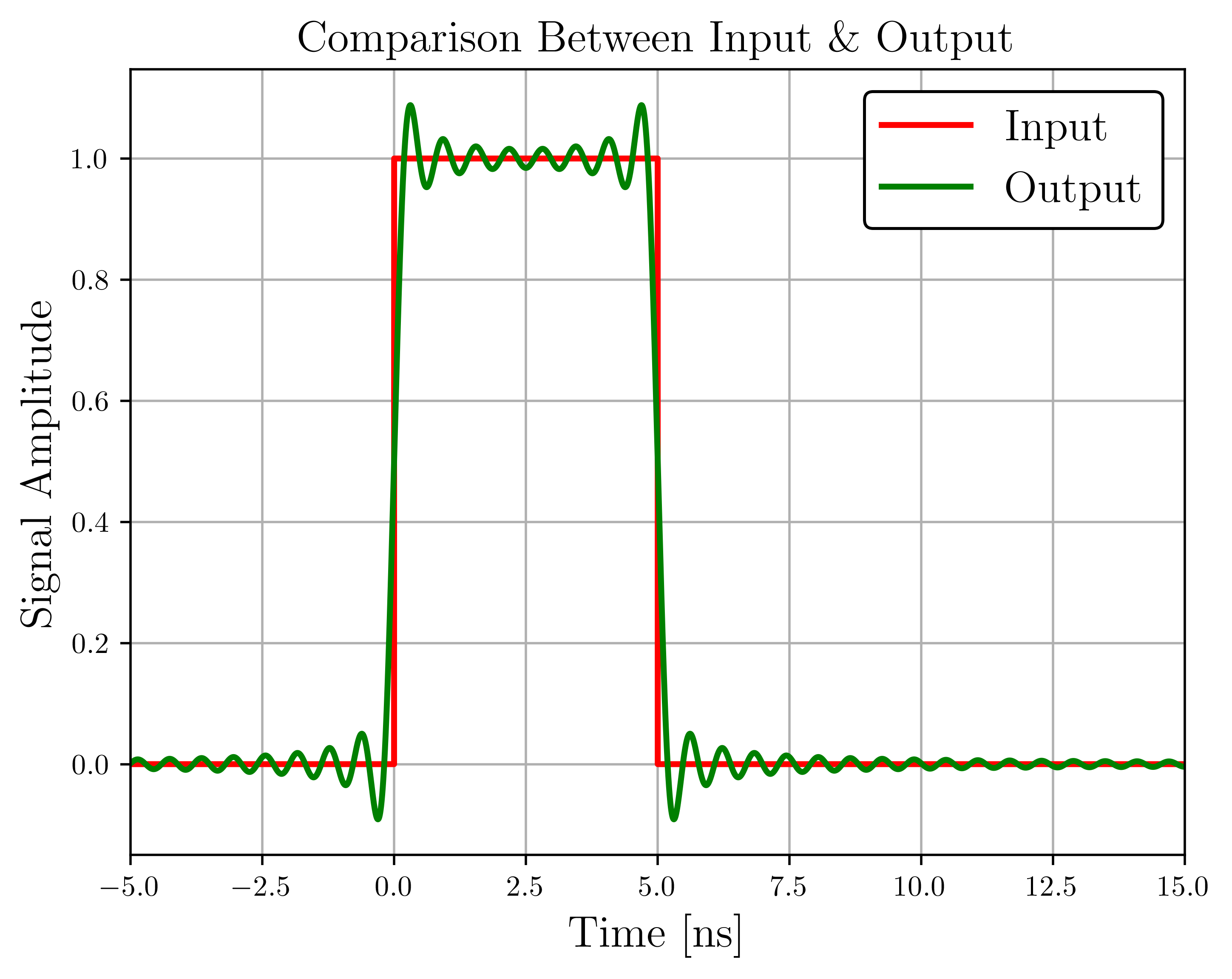
The amplifier of my system has a bandwidth of 10 kHz $-$ to 2 GHz @ 40 dB, and I would like to simulate pulses sent to it in python. By inputing a square pulse inside the amplifier (of 5ns of duration), and following the procedure described above, assuming 0 phase shift at all frequencies and infinitely sharp corners around the bandpass, I got: enter image description here

(Results are normalised) Now, I think it is obvious that this can never happen in real life, since the output signal starts before the original input wave, thus violating causality. How can one modify the modeling of the system such that the output signal is causal? I also believe that this has to do with the delay response as well. How can someone construct a causal impulse response, from the gain and phase frequency response?

$\endgroup$
4
  • $\begingroup$ Do you have the filter design of your amplifier, or is it a purchased unit, or is it hypothetical? If you have the schematic you can calculate the response, if it's a purchased unit then you want to see if they have a step response or pulse response -- and if they don't and you want to put pulses through it, then you may want to seriously consider a different amplifier. $\endgroup$
    – TimWescott
    Commented Dec 14, 2022 at 21:54
  • $\begingroup$ @TimWescott Many Thanks for the reply. The company does not unfortunately provide the design. I have tried to contact them but they don't reply. The question however is mainly theoretical in nature, and asks how to construct the impulse response from the Gain and Phase Response functions (with at the same time, preserving causality). $\endgroup$
    – Heath
    Commented Dec 14, 2022 at 22:06
  • $\begingroup$ Please edit your question to incorporate the information, BTW. $\endgroup$
    – TimWescott
    Commented Dec 14, 2022 at 22:06
  • $\begingroup$ Gain and phase together fully specify the filter response. Once you've chosen both you have the frequency response; the impulse response is just the inverse Fourier transform of that and it is either zero for all time $t < 0$ or it's not. $\endgroup$
    – TimWescott
    Commented Dec 14, 2022 at 22:10

2 Answers 2

2
$\begingroup$

Assuming that you've checked that for your application the amplifier can be accurately modelled as a linear system, you need to choose a square-integrable gain response $A(\omega)$ that satisfies the Paley-Wiener condition:

$$\int_{-\infty}^{\infty}\frac{\big|\ln\{A(\omega)\}\big|}{1+\omega^2}d\omega<\infty\tag{1}$$

If $(1)$ is not satisfied, then there is no causal system with the given gain response $A(\omega)$. Clearly, a function $A(\omega)$ that is zero on any finite interval cannot satisfy $(1)$.

On the other hand, if a gain function $A(\omega)$ satisfies $(1)$, we only know that there exists a causal system with that gain response, but we don't know how to find its phase. Clearly, even if $(1)$ is satisfied for a certain gain function $A(\omega)$, the corresponding system could still be non-causal depending on the chosen phase function.

One way to make sure that the system is causal is to choose a gain function $A(\omega)$ satisfying $(1)$, and combining it with a phase function such that the resulting system is a minimum-phase system. For minimum-phase systems, the attenuation $\ln A(\omega)$ and the phase are related by the Hilbert transform, so the phase can be computed from $A(\omega)$ (as long as $(1)$ is satisfied). Simple choices that will guarantee causality and the minimum-phase property are standard filter responses such as Butterworth, Chebyshev, and Cauer (elliptic) filters.

But you can also specify some $A(\omega)$ satisfying $(1)$ and try to compute the phase of the corresponding minimum-phase system via the Hilbert transform. A very simple example would be a piecewise constant gain function with gain $1$ in the passband, and gain $0<A_s\ll 1$ in the stopband. If $\omega_c$ denotes the cut-off frequency, the resulting phase of the corresponding minimum-phase system can be computed as

$$\phi(\omega)=-\frac{\ln A_s}{\pi}\ln\left|\frac{\omega-\omega_c}{\omega+\omega_c}\right|\tag{2}$$

This system is a causal, minimum-phase brickwall lowpass filter with an arbitrarily small but non-zero stopband attenuation $A_s$.

$\endgroup$
0
$\begingroup$

How can someone construct a causal impulse response, from the gain and phase frequency response?

You can't. The gain and phase frequency response together fully specify the time-domain impulse response. This is because the Fourier transform is fully invertible. I.e., a filter's gain and phase response are the amplitude and angle of its frequency response $H(\omega)$; it's frequency response is the Fourier transform of it's impulse response $h(\tau)$.

$$\begin{align} H(\omega) &= \mathcal F \{h(\tau)\} \\ h(\tau) &= \mathcal F^{-1} \{H(\omega)\} \end{align}$$

Both the Fourier transform ($X(\omega) = \mathcal F \{x(t)\}$) and the inverse Fourier transform ($x(t) = \mathcal F^{-1} \{X(\omega)\}$) are 1:1 mappings between the time domain and the frequency domain. So a fully-specified $H(\omega)$ implies a fully-specified $h(\tau)$ - and visa versa.

How can one modify the modeling of the system such that the output signal is causal?

In the case you've given -- you can't, really. You've chosen a "brick wall" filter, which you cannot make a causal version of (or you can in theory, but you can't in practice).

Filter design is a good part of the art of signal processing, because coming up with realizable filters that do what you want and don't break the bank is hard. This applies to both digital signal processing, and to analog electronics design. So it's not something that can be easily summarized in one StackExchange answer.

Typically, though, you choose a desired filter response, be sure to include "don't care" regions, with the knowledge that the narrower you make the "don't cares" the more expensive your filter is going to be, then you either fit one of the standard filters (Butterworth, Tchebychev, Elliptical, etc.) to it, or you use one of the known filter design algorithms to make you a filter. Then you review the result to see if it's good enough and realizable. Then you actually build it and find out if your "cheap and realizable" hypothesis was correct.

In the case of your amplifier, since it's an actual electronic circuit, it may be best to just assume a common filter type (see above) and use one of those frequency responses. Note that an amplifier with the specifications you give will almost certainly have two filters: a simple high-pass filter with a lower cutoff at 10kHz, that may even be one pole (i.e. $H_{hp}(\omega) = \frac{s}{s + \omega_0}$, with $\omega_0 < 2 \pi 10^{4} \mathrm{Hz}$), and a low-pass filter with a cutoff around 2GHz that will almost certainly not be a nice tidy Butterworth, Tchebychev, etc., because it may well be realized with non-lumped circuit elements, and because the circuit designer may not be driven by the same implied requirements as you.

In the absence of documentation, I'd take the amplifier, hook it up to a really fast signal generator and a really fast oscilloscope, and just measure the response to a pulse.
$\endgroup$

Your Answer

By clicking “Post Your Answer”, you agree to our terms of service and acknowledge you have read our privacy policy.

Not the answer you're looking for? Browse other questions tagged or ask your own question.