0
$\begingroup$

I don't really understand maths behind filtering but use it lot in music production and i'm a total newbie to DSP.

Usually parametric filters let you filter frequencies with a precision that seems almost infinite. But when using a FFT or DFT the taken window size gives n / 2 + 1 frequency bands.

Are the two related ? if so how can a filter get so much precision when Fourier Transform doesn't?

That may seem a dumb question but when I look at spectrograph in sound softwares they always looks much more precise than the buffer I've choosed (usually 256 samples).

$\endgroup$

2 Answers 2

1
$\begingroup$

It is simply because the FFT (which implements the DFT, Discrete Fourier Transform) is intended to provide (very efficiently) the results of bandpass filters centered on every bin. The easiest way to explain this is to consider the 4 point DFT and compare that to 4 point moving average filters and to show what we do to center the moving average filter on any given frequency with infinite precision.

Consider the 4 point DFT:

$$X[k] = \begin{bmatrix}1 & 1 &1 &1 \\1 & -j & -1 & j\\1 & -1 & 1 & -1 \\1 & j & -1 &j \end{bmatrix}\begin{bmatrix} x[0] \\ x[1] \\x[2]\\x[3]\end{bmatrix}$$

Notice the first row, which is the 0 frequency bin, is just the sum of the 4 samples of x. If we were to move through a larger data set, taking 4 samples at a time and computing the DFT, and then shifting by one sample and repeating this, then the first bin results would be EXACTLY the same as a moving average filter (note the reverse order of the coefficients in the structure showing the position of the samples of x after the first 4 samples):
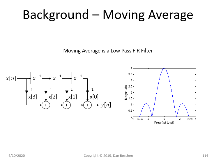
Moving average filter

Another key point with the moving average filter, if we rotate the coefficients, we translate the filter to the center frequency of that rotation. That is exactly what the other rows are: Notice row 2 is rotating clockwise one cycle. Thus the DFT is a bank of filters:
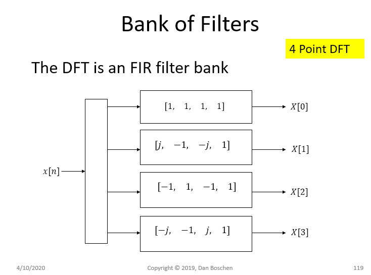
bank of filters

And here is the frequency response for each bin of the 4 point DFT. The horizontal axis in this plot is going from $0$ to $2\pi$ where $2\pi$ is the sampling rate. While the previous plot above is centered on zero going from $-\pi$ to $\pi$. (Similar to what the MATLAB command fftshift provides.
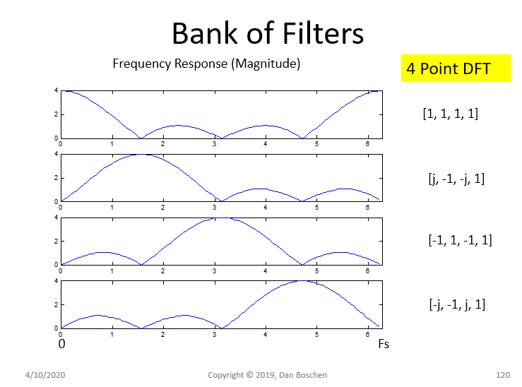
bank of filters magnitude

So because the DFT provides distinct rotations centered on each bin we get the results as a filter centered on each bin. To center the moving average filter on any other frequency (with infinite precision), simply rotate at that exact frequency.

For the example of the 4 point moving average, the coefficents would be given as

$$c_n = \sum_{n=0}^3 e^{j\omega_n n}$$

Where $\omega_n$ is the normalized angular frequency between $0$ and $2\pi$.

I demonstrate this below using $\omega_n = 1$ resulting in the coefficients

$$[e^{j0}, e^{j1}, e^{j2}, e^{j3}]$$
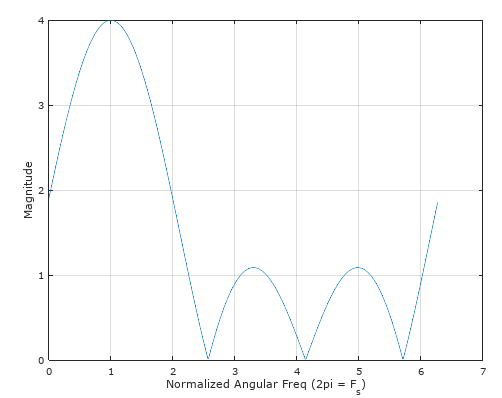
enter image description here

$\endgroup$
5
  • $\begingroup$ I think I'lll be able to understand that in a long time. Many thanks for your answer. I'll surely take a deeper look into it. ;) thanks $\endgroup$
    – JSmith
    Commented Apr 10, 2020 at 14:31
  • $\begingroup$ @JSmith it may help you to realize (if you didn't) that the expression $Ke^{j\theta}$ is simply a vector with magnitude $K$ and angle $\theta$ $\endgroup$ Commented Apr 10, 2020 at 15:04
  • $\begingroup$ Haha I had a look and honestly this seems like a foreign language to me . Started reading The scientist and enginer's Guide to Digital Signal Processing of Steven W . Smith but honestly even trying to understand step by step is not as fluent as I would like. Anyway great explanation of yours thanks again . $\endgroup$
    – JSmith
    Commented Apr 10, 2020 at 15:08
  • $\begingroup$ @JSmith download Octave (free) and play with this stuff directly and it will start to make more and more sense. Stick with it! Spend a LOT of time looking at correlation which is the sum of products and what happens to signals and noise when you sum (or average). This is the basis of MANY signal processing concepts including the Fourier Transform, Laplace Transform, filtering, receivers, Viterbi decoding, etc etc etc you will see that sum of products (or multipy and integrate in the analog domain) show up again and again so I recommend you get your head around that. $\endgroup$ Commented Apr 10, 2020 at 15:09
  • $\begingroup$ thanks for the advice. I'll do that $\endgroup$
    – JSmith
    Commented Apr 10, 2020 at 15:10
2
$\begingroup$

The DFT is a tool to represent the spectrum of any signal. Usually for an N point DFT only N/2 output coefficients are required because for a real signal the DFT is symmetric about the centre.

No filter has infinite precision, neither infinite bandwidth nor numeric representation. A filter with enough precision can be chosen for an application to seem smooth enough.

The DFT though doesn't have anything to do with a filter. It simply represents the spectrum of the signal at it's input.

$\endgroup$
2
  • $\begingroup$ ok thank you for your answer that's what I though. Many Thanks $\endgroup$
    – JSmith
    Commented Apr 10, 2020 at 14:15
  • $\begingroup$ You are welcome $\endgroup$ Commented Apr 10, 2020 at 14:23

Your Answer

By clicking “Post Your Answer”, you agree to our terms of service and acknowledge you have read our privacy policy.

Not the answer you're looking for? Browse other questions tagged or ask your own question.