0
$\begingroup$

I'm trying to transmit and receiver the GPS payload in both Time and Frequency Domain.

For transmitting and receiving in time domain :

numBits = 10;                        % LFSR length
codeLength = 2^numBits-1;           % Spreading code length 

payload1 = 1*(rand(1,100)>0.5);
payload2 = 1*(rand(1,100)>0.5);
payload3 = 1*(rand(1,100)>0.5);

payload1 = 2*payload1 - 1;            %BPSK Modulation 
payload2 = 2*payload2 - 1;            %BPSK Modulation 
payload3 = 2*payload3 - 1;            %BPSK Modulation 

%  payload1 = ones(1,10);
%  payload2 = ones(1,10)*2;
%  payload3 = ones(1,10)*3;
%% PN code generation

% initial sequence is taken from IRNSS document
goldCode1 = generateGoldCode(935,239,codeLength,numBits);
goldCode1 = 2*goldCode1-1;                        % Assign code to 1 to 1 and -1 to 0

goldCode2 = generateGoldCode(38,381,codeLength,numBits);
goldCode2 = 2*goldCode2-1;

goldCode3 = generateGoldCode(564,561,codeLength,numBits);
goldCode3 = 2*goldCode3-1;

%% At transmitter part 
payloadData1 = kron(payload1,goldCode1);         % Product of payload data and gold code to spread the sequence
payloadData2 = kron(payload2,goldCode2);    
payloadData3 = kron(payload3,goldCode3);


TxData = (payloadData1 + payloadData2 + payloadData3);

%% At receiver part 
%% Time Domain 
crossCorr = xcorr2(TxData,goldCode2);              
outputData = crossCorr(codeLength:codeLength:end)/codeLength;

For Frequency domain I want to receive each bit at a time:

starting =1;
i=0;
crossCorr_temp=[zeros(1,100)] ;
goldCodeFFT = conj(fft(goldCode2));
for val = 1023:1023:length(TxData)
  payloadFFT = fft(TxData(starting:val));
  crossCorr_FFT = ifft(payloadFFT .*goldCodeFFT);
  corr_time = crossCorr_FFT(1:end)/codeLength; **#Doubt here**
  starting = starting +1023;
  i=i+1;
end

How do I approach this frequency-domain way to receive the GPS payload bits?

$\endgroup$
1
  • $\begingroup$ Why do you multiply each payload by a different constant (1,2,3)? Are you emulating different received signal strength of each? To start to address real receiver issues, you'll want to introduce a random Doppler offset (anywhere within + /- 2.5KHz would be typical), a random sampling time offset (so you will want to have multiple samples per chip to do this), and a random starting position offset in your receiver. If you can deal with all three of those uncertainties in your receiver you will be prepared to receive actual signals. $\endgroup$ Commented Dec 26, 2019 at 13:39

1 Answer 1

1
$\begingroup$

I do not see any issues with your approach for the frequency domain computation, given that the following is a circular convolution in the time domain of the two signals a and b:

$$corr(a,b) = ifft(fft(a)fft(b)^*)$$

But to receive each bit you need to evaluate the maximum in each interval to determine if it is positive or negative.

Further in actual application, the received signal would be sampled higher than one sample per bit, with the unknown Doppler offset frequency removed (carrier recovery) and aligned such that your start of the FFT is at the start of the symbol. There are also 20 1023 length symbols per actual data bit in GPS.

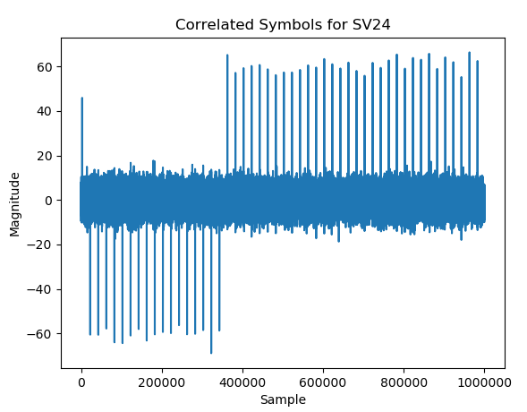
In this case the FFT would be rate matched to the received signal. You could also process longer blocks as I show in the example plot below, by simply zero padding the rate-matched prn sequence out to the length of the data block prior to taking the FFT. In the plot below this was done for 1e6 samples of actual received signals sampled at 20 MSps.

Correlated GPS

$\endgroup$
2
  • $\begingroup$ Got it mate thanks $\endgroup$ Commented Dec 26, 2019 at 14:20
  • $\begingroup$ please check off the answers to your questions you receive as correct if they resolved your issue (or leave it as is if you are looking for a better answer) $\endgroup$ Commented Dec 26, 2019 at 17:18

Your Answer

By clicking “Post Your Answer”, you agree to our terms of service and acknowledge you have read our privacy policy.

Not the answer you're looking for? Browse other questions tagged or ask your own question.