How do you implement Direct Sequence Spread Spectrum (DSSS) to synchronize the spreading rate with the symbol rate when there is a non-integer but rational relationship between the two?
-
1$\begingroup$ Where do these numbers come from? For BPSK, 8192 bits/second is 8192 symbols/second, and so you have $\frac{6.138*10^6}{8192}=749.2676$ chips per symbol. Seems a bit weird to me without any context $\endgroup$– EngineerCommented Dec 9, 2019 at 13:43
-
1$\begingroup$ Why do you feel they need to be synchronized? Why can’t you simply multiply the data with the spreading pattern? The waveform sampling rate just needs be high enough to support doing this. $\endgroup$– Dan BoschenCommented Dec 9, 2019 at 13:45
-
$\begingroup$ @DanBoschen I don't think she is asking about synchronous vs asynchronous but how to implement the spreading for the rates she listed $\endgroup$– EngineerCommented Dec 9, 2019 at 19:57
-
$\begingroup$ Yes that is what I meant about synchronous: the spreading chips need not be an integer multiple of the data chips- so simply multiply the two waveforms. One sample per chip would be fine in the transmitter and 2 samples per chip in the receiver for acquisition and timing recovery. $\endgroup$– Dan BoschenCommented Dec 9, 2019 at 20:29
-
1$\begingroup$ @Samantaricher I updated my answer with an example reference. On that go to page B-2 that describes it most clearly: "Coherent and Non-coherent Modes: In the system described, the PN code clock is synchronous with the RF carrier but the User data clock is not expected to be coherent with either." $\endgroup$– Dan BoschenCommented Dec 10, 2019 at 12:37
1 Answer
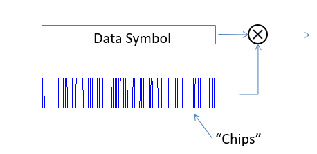
There is no requirement that Direct Sequence Spread Spectrum (DSSS) have an integer number of chips per symbol, nor for the repetition rate of the code to be synchronous with the data (although this is often done). So in this case you have a spreading sequence with a code of some particular length that is running at 6.138Mcps that is multiplied by your data at the lower rate of 8192 symbols/second. This would not change typical approaches in the receiver to demodulate the DSSS signal, where you would perform the same multiplication and integrate over a data symbol duration (correlator). Along with all the usual approaches to timing and carrier recovery and signal acquisition such as three half chip spaced correlators for Early-Prompt-Late or if processing allows block FFT-based fast acquisition.
One example where this is done is described in this link:
https://public.ccsds.org/Pubs/415x1b1.pdf
I assume your challenge is how to do the spreading specifically in your case, knowing that you simply multiply the two waveforms as I show above. One approach to do this is to resample your data to match the chip rate and then multiply sample by sample:
Notice that the relationship between the chip clock and data clock is 6138000/8192 which is exactly $749 + 137/512$
A simple way to do this is to use a 9 bit counter that rolls over at 512, such that you send 749 chips for every sample and then add 137 to your counter at the end of each data symbol ($count[n] = (count[n-1] + 127) mod 512$)- if the counter rolls over then add one more chip to that data symbol. The first 5 data symbols and the counter value at the end of each symbol would proceed as follows:
Symbol 1: counter = 0+ 137 no rollover : 749 chips
Symbol 2: counter = 137 +137 = 274 no rollover: 749 chips
Symbol 3: counter = 274 + 137 = 411 no rollover: 749 chips
Symbol 4: counter = 411 + 137 = 548 rollover 548%512= 36: 750 chips
Symbol 5: counter = 36 + 137 = 173 no rollover: 749 chips
-
$\begingroup$ I think this is correct. Why downvote? $\endgroup$– AlexTPCommented Dec 10, 2019 at 10:02
-
$\begingroup$ @ AlexTP can you give an example? $\endgroup$– user46622Commented Dec 10, 2019 at 10:52
-
$\begingroup$ @Samantaricher see the update of this answer. $\endgroup$– AlexTPCommented Dec 11, 2019 at 15:37
-
$\begingroup$ @DanBoschen At the receiver, you have a correlator over the 749 chips and another correlator over the 750 chips? $\endgroup$– EngineerCommented Dec 11, 2019 at 16:03
-
$\begingroup$ That is essentially what would happen - same correlator but changing when you actually dump (for an integrate and dump correlation approach)- but the timing recovery loops for the chip clock and data clock in the receiver (once in tracking) would naturally do this—- so you let the loops take care of that. $\endgroup$ Commented Dec 11, 2019 at 16:40

