3
$\begingroup$

Interpreting some homework, I'm a little confused on what it's asking for. I'm asked to filter in the frequency domain (easy enough, just a fft2 and ifft2 when I'm done) a 256x256 8bit grayscale tiff with the following filters:

  • "Rectangular low pass filter using cutoff frequency of (uc=N/4,vc=M/4) where N and M are the row and column sizes of the image."
  • "Circular low pass filter using cutoff frequency of Circular
    filter the cutoff frequency is given by Rc=N/4= sqrt[(uc)^2+(vc)^2]
    where N and M are the row and column sizes of the image"
  • "Rectangular high pass filter that has the same cutoff as part a."
  • "Circular high pass filter that has the same cutoff as part b."

Now, I understand some of this well enough, but the "Rectangular/Circular" throw me. We didn't really cover anything like that. What we did cover were the ideal low/high pass filters and the butterworth low/high pass filters. Is this perhaps a synonym for the two, the ideal with its immediate cutoff and the buttworth with its tapering? My book does not mention anything in this regard (though perhaps I have not found it...the book is verbose and I am an impatient student at times), only that the general form it gives for the Ideal filters is a circular cutoff, which is what prompts my second supposition: that the circular is the method the book uses, and the rectangluar means to filter anything inside a submatrix one quarter the size of my image, centered, in the frequency domain.

Or are we talking two different kinds of ideal LPFs and HPFs,

Yes, this is homework for a course, but I'm not looking for easy answers. I'm looking for understanding.

$\endgroup$
1
  • $\begingroup$ so, could you please give a response if something is missing or if your answer is completed? $\endgroup$
    – mchlfchr
    Commented Oct 17, 2012 at 6:23

3 Answers 3

4
$\begingroup$

You're probably best off asking your professor for clarification. As you reasoned, it sounds like you're being asked to multiply the image in the frequency domain by either a rectangular or circular mask that eliminates all frequencies outside the mask. This is not typically how you would apply a filter, however, as "ideal" frequency-domain filter masks have unsatisfactory time-domain properties (e.g. a truly ideal rectangular filter has an infinitely long impulse response).

As you noted, filters with a tapered response (of which the Butterworth filter is an example) are more often used. However, the problem specification doesn't seem to contain the information that you would need to design such a filter, such as the type of filter and its order.

$\endgroup$
2
$\begingroup$

Well, you're talking about FFT filtering, right? So you're transforming to the frequency domain, multiplying by a filter, and then inverse transforming back into the image domain ("space domain"?)

So what is the filter that you're multiplying by? Another image, with values of 1 for the frequencies that should be kept, and values of 0 at the frequencies that should be filtered out, etc.

If you understand how the frequency axes are mapped in your 2D FFT implementation, you can see that this filter can be drawn as a white square or a white circle.

$\endgroup$
2
$\begingroup$

The frequency domain is organized into a frequency distribution. For visual understandings you often see images, which have polar coordinates and the magnitude/power spectrum displaying for frequency domain. Some shifting of the quadrants is also done.

Lower frequencies are in the middle of the image while higher frequencies are going to the corners. This depends on the magnitude properties of lower and higher frequencies.

The cutoff for a low pass filter (LPF) itself describes the ammount of low-frequencies you let pass through your filter. The rest is cut off.

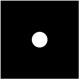
The sharp cutoff (like in the ILPF (See 1) or IHPF) of a frequency filter leads to ringing of your signal in spatial/time domain, which is not quite good and creates artifacts.

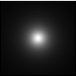
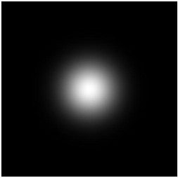
Therefore you fade your frequency filter to the edges, in order to minimize the artifact generation in spatial domain. The Butterworth and the Gauss filter are using these technique (See Image 2 and 3). The $D_0$ of Gauss and Butterworth is describing the fading factor or commonly said how fast the fade to black/white takes place.

You can design your filtermasks circular or like a rectangle (box). The images of the low pass filtermasks should give you a better understanding of what I posted above. It is also valid for rectangular shapes.

ILPF BLPF GLPF

The high pass filters (HPF) are inverted.

$\endgroup$

Your Answer

By clicking “Post Your Answer”, you agree to our terms of service and acknowledge you have read our privacy policy.

Not the answer you're looking for? Browse other questions tagged or ask your own question.