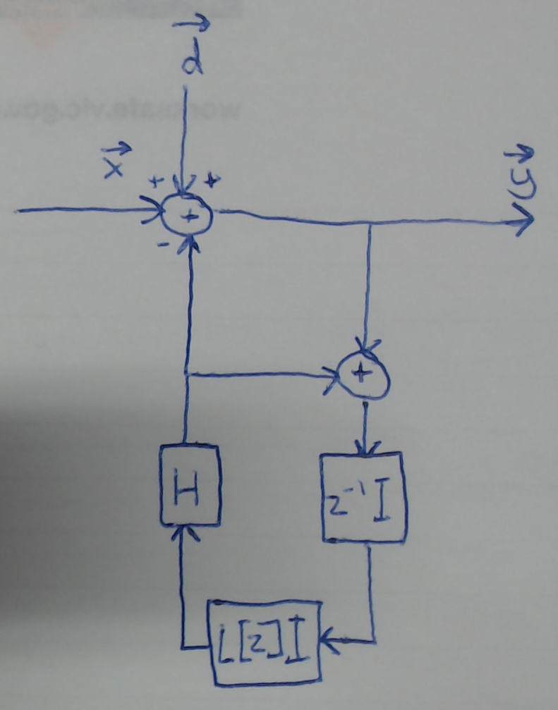
FIR filters are typically a bad idea to include in the feedback of a control loop, unless the system is significantly oversampled such that the delay of the filter is insignificant. If an additional filter is to be used, care should be made to implement a minimum phase filter with review of system stability. The stability of a simple loop like this is easily determined from the Bode Stability criterion (in general when working with unstable plants using the Nyquist Criterion would be more robust): The Bode Stability Criterion is to review the frequency response for the "open loop gain" and ensure that the phase does not surpass -180° while that magnitude of the gain in dB is still positive.
For this simple loop, without considering yet the filter given by $H(z)$, the open loop gain is frequency response of the unit sample delay cascaded with the accumulator. We get the frequency response by replacing $z$ with $e^{j\omega}$ in the transfer function, where $\omega$ is the normalized radian frequency in units of radians/sample ($\pi$ corresponds to the Nyquist frequency $f_s/2$, where in this case $f_s$ is the OP's sweep repetition rate). The transfer function of the unit delay is $z^{-1}$ and the transfer function for the accumulator is $1/(1-z^{-1})$. Cascading the two results in the open loop transfer function or "open loop gain":
$$G_{OL}(z) = \frac{z^{-1}}{1-z^{-1}}$$
We can solve this simple case manually, but in general the frequency response (as the DTFT for a digital system) is readily provided by the function freqz which is available in MATLAB, Octave and Python's scipy.signal library) demonstrated below:
import scipy.signal as sig
w, h = sig.freqz([0, 1], [1, -1])
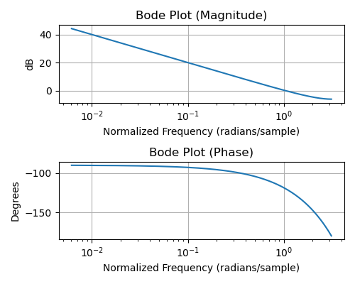
We see that without the filter even included, there is about 60° of phase margin when the frequency reaches the 0 dB crossing (which is where the loop BW would be). If the delay of the additional filter results in a phase that exceeds -60° at this frequency, the closed-loop system will be unstable, and even if it is less than -60°, as the phase margin decreases below approximately 35°, significant ringing in a step changes will result. A single additional unit sample delay (let alone multiple delays as done with an FIR filter implementation) has a phase versus frequency transfer function that goes from 0 to -180° as the frequency extends from DC to Nyquist, thus it is clear that even one more sample delay in the OP's loop will result in instability.
In general it is good practice to let the control loop itself do the filtering (it is a filter!): With the accumulator (digital integrator) alone the result would be a first order loop and thus provide filtering of -20 dB/decade beyond the loop bandwidth (which is set by adjusting the gain of the input to (or output from) the accumulator. For tighter filtering (and to track first order dynamics to zero error) you can add a second accumulator, but this would also necessitate a proportional term (to be a second order Proportional-Integral or PI loop). When the system is significantly oversampled, an additional low-pass filter with a cut-off much higher than the loop bandwidth would also have proportionally much less delay, so it is for these cases, if done properly, that additional filtering can be included.
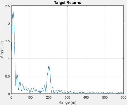
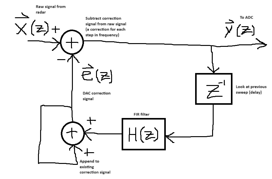 I have already implemented this, and it mostly works. The issue is that over time, the impulse response from the FIR filter seems to build in the DAC correction signal (at both the start and end, because of forward and backward filtering?) and thus builds in the return signal. Below is a screenshot of the raw IFQ response when using this method with a low pass FIR filter (trying to remove close targets) while the radar pointed at the same target ~2 meters away for several hours while sweeping with a 1 GHz bandwidth trapezoidal chirp.
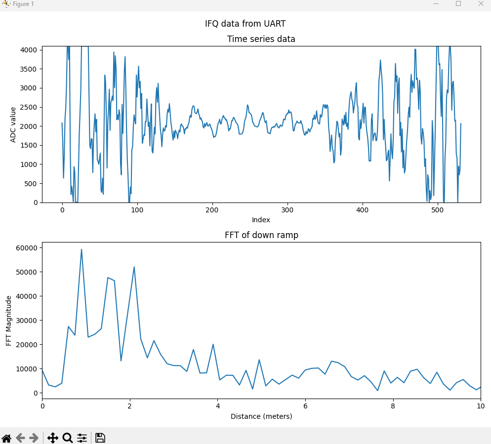 Is there an obvious reason why this happens? I'm having a hard time finding explanations or causes, so I wanted to ask here. Also, I apologize if this is too poor/vague of a description. Please let me know if there's any context that could help describe this scenario.

