Your problem is that you have a multiple input multiple output system which couples the elements of your sweep, thus we indeed expect the edge effects of your zero-phase digital FIR filter to work their way inwards. To analyse your system, because your correction term is a cumulative sum of the vectors output from your FIR filter (that is, the "append to existing correction signal"), you can consider that at each sweep you get a vector of inputs, rather than a timeseries of data, with the transfer function of your system being: $$\mathbf{y}=\mathbf{x}-\left(\frac{1}{1-z^{-1}}\mathbf{I}\right)\mathbf{H}\left(z^{-1}\mathbf{I}\right)\mathbf{y}=\left(\mathbf{I}+\frac{z^{-1}}{1-z^{-1}}\mathbf{H}\right)^{-1}\mathbf{x}$$$$\mathbf{y}=\mathbf{x}-\left(\frac{1}{1-z^{-1}}\mathbf{I}\right)\mathbf{H}\left(z^{-1}\mathbf{I}\right)\mathbf{y}=\left((z-1)\mathbf{I}+\mathbf{H}\right)^{-1}(z-1)\mathbf{x}$$ Where lower case boldface are vectors, and upper case boldface are matrices ($\mathbf{I}$ being the identify matrix). That matrix $\mathbf{H}$ (your FIR filter) is coupling everything, which is why it's expected that the edge effects will work their way inwards. To assess stability, you'dyou have to solve the following, which gives the pole locations: $$\mathbf{det}\left(\mathbf{I}+\frac{z^{-1}}{1-z^{-1}}\mathbf{H}\right)=0$$$$\mathbf{det}\left(z\mathbf{I}-(\mathbf{I}-\mathbf{H})\right)=0$$ ThisThe solutions for $z$ (the pole locations) can be recognised as the eigenvalues of $\mathbf{I}-\mathbf{H}$. Your system is much more complexstable if the magnitudes of all the solutions are less than things need to beone, as usual for z domain transfer functions (that is, if all the poles are inside the unit circle).
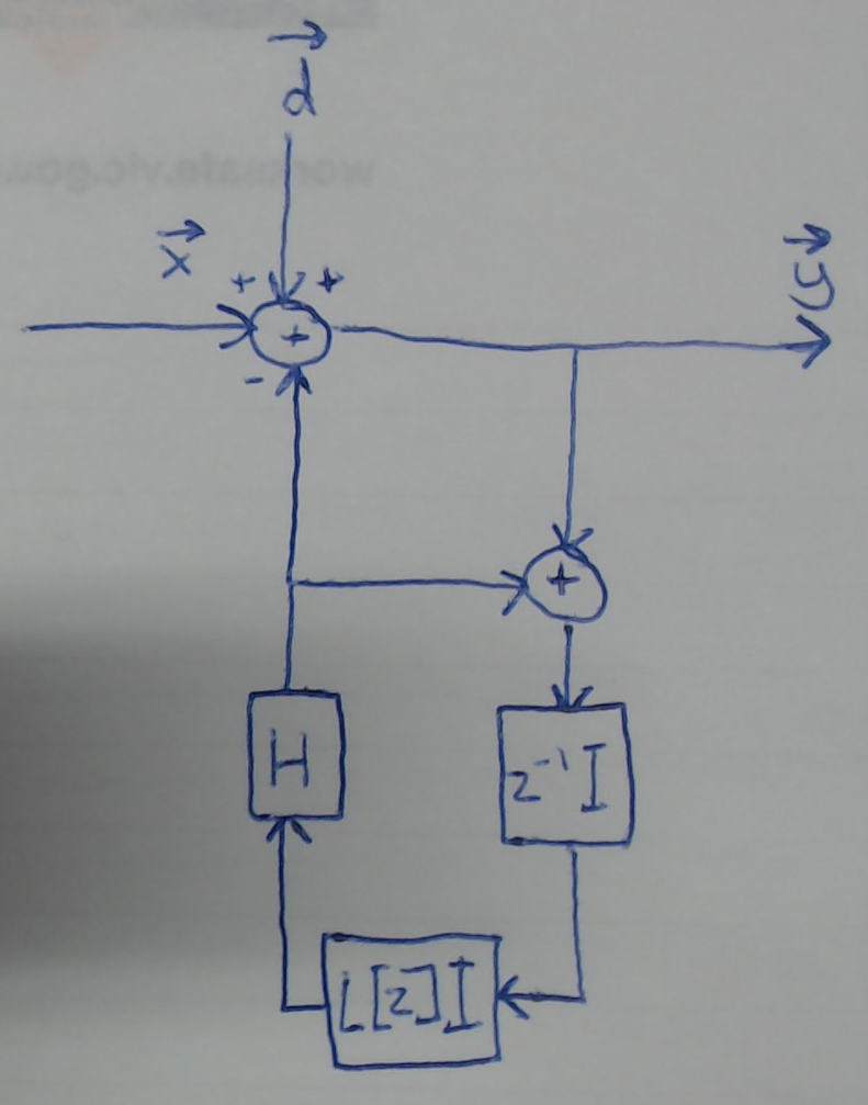
As a simpler solution, redesign your control loop as per my figure below, which that will guarantee stability and prevent the edge effects creeping inwards, withredesign your control loop as per the figure below, which has the transfer function given by: $$\mathbf{e}=\mathbf{H}\left(L[z]z^{-1}\mathbf{I}\right)(\mathbf{e}+(\mathbf{x}-\mathbf{e}+\mathbf{d}))=\mathbf{H}L[z]z^{-1}(\mathbf{x}+\mathbf{d})$$ $$\mathbf{y}=\mathbf{x}-\mathbf{e}+\mathbf{d}=\left(\mathbf{I}-\mathbf{H}L[z]z^{-1}\right)(\mathbf{x}+\mathbf{d})$$ Where $L$ is the transfer function of a low pass filter to provide some averaging of uncorrected sweeps (probably a moving average filter will do, but I'll leave that decision to you), and I have included a disturbance, $\mathbf{d}$, to be more rigorous because I presume your DAC and ADC will have some inaccuracy that is uncorrelated with the signal (e.g. noise). This system has no poles, except possibly in the low pass filter, $L$, so design a stable low pass filter, and you're guaranteed a stable system. Hopefully that final transfer function is quite intuitive in that, ignoring the disturbance, $\mathbf{d}$, it takes $\mathbf{x}$ and subtracts the component you don't want to give you $\mathbf{y}$, which is exactly what you want it to do. Note that the role of the low pass filter is to just give some averaging between sweeps to attenuate their noise, which I guess you're aware of the need for since you used that cumulative sum, and in fact this is really to try to attenuate the effect of $\mathbf{d}$ on your correction. On the first iteration, I would initialise the low pass filter so that its output immediately is equal to the first sweep signal, like what your integrator did.

