0
$\begingroup$

i'm trying to implement SSB Modulation on Octave. i based my code on this:

https://www.mathworks.com/help/signal/ug/single-sideband-modulation-via-the-hilbert-transform.html

it works ok, until i change Fo to a higher frequency, in MHz (of course, changing the Fs>2*fo on ssbdemod also). when i do it, the demod sounds metallic, and when analyzing spectrum, it doesnt seem to supress the other sideband well.

here is what i have been doing:


pkg load signal
pkg load communications

[input_wave, Fs] = audioread('./input.wav');

t = (0:length(input_wave)-1) / Fs;

N = 60;
h = firpm(N, [0.05 0.95], [1 1], 'hilbert');

input_wave_tilde = filter(h, 1, input_wave);

G = floor(N/2);

fo = 1000;
input_wave_delayed = [zeros(1,G), input_wave(1:end-G)];
input_wave_tilde_delayed = [zeros(1,G), input_wave_tilde(1:end-G)];

t = (0:length(input_wave_delayed)-1) / Fs;

f = input_wave_delayed .* cos(2*pi*fo*t) - input_wave_tilde_delayed .* sin(2*pi*fo*t);

demodulated_signal = ssbdemod(f, fo, Fs);

demodulated_signal = demodulated_signal / max(abs(demodulated_signal));

output_path = './demodulated_signal.wav';
audiowrite(output_path, demodulated_signal, Fs);


Thanks in advance!

$\endgroup$

1 Answer 1

1
$\begingroup$

It appears you may be changing fo to a rate above Nyquist (Fs/2). As a .wav file, the sampling rate is likely 44.1 KHz or 48 KHz, so fo must be sufficiently less than half of that to avoid aliasing issues.

It may be more instructional as well as simpler to do the demodulation without use of the communications toolbox. To demodulate SSB, you can simply reinsert the missing carrier frequency fo, (by adding A * cos(2*pi*fo*t) with an A that is bigger than the peak deviation of your waveform (to ensure SSB with a large carrier) and then detect the envelope of the result. The envelope is found from the absolute value of the analytic signal; the analytic signal is what the hilbert function returns:

demod = abs(hilbert(ssb_wave + A * cos(2*pi*fo*t))) - A;

(The -A is to optionally remove the DC term from the demodulated symbol, similar to subtracting the mean).

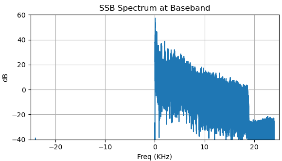
We can also create the SSB signal at baseband using the hilbert function since the analytic signal is exactly that: the positive frequencies only or the equivalent of SSB at baseband:

ssb_base = hilbert(input_wave);

Plotting the spectrum of ssb_base for an example wav file further demonstrates what I described above:

SSB baseband spectrum

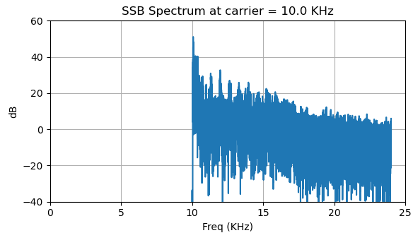
ssb_base is a complex waveform (consistent with any spectrum that is not complex conjugate symmetric as all real waveforms must be, and thus we would need "I" and "Q" signals to implement this as we have it as baseband resulting in an "I+jQ" baseband signal). What this allows us to do, as we would in an actual implementation, is translate the signal to a higher carrier frequency using a complex local oscillator, after which we can take the real part for our passband waveform:

fo = 10e3;
ssb_wave = real( exp(1j* 2 * pi * fo * t) .* ssb_base );

SSB spectrum at fo

Also note that when we do use complex baseband signals, "DC" is a carrier frequency just like any other frequency (it just has a frequency = 0). This simplifies a lot of simulations as we avoid having to simulate the actual carrier itself. For example, here we could SSB demodulate the baseband signal we created using:

demod = abs(A + ssb_base);
$\endgroup$
2
  • $\begingroup$ thank you so much for the explanation! now i got it working. now its time to apply it on the microcontroller then to a mixer $\endgroup$
    – SoxxZ _
    Commented Apr 28 at 20:02
  • $\begingroup$ Great! Please select if I answered your question to close this out and have fun with your interesting project! $\endgroup$ Commented Apr 28 at 20:15

Your Answer

By clicking “Post Your Answer”, you agree to our terms of service and acknowledge you have read our privacy policy.

Not the answer you're looking for? Browse other questions tagged or ask your own question.