0
$\begingroup$

I need to implement some sort of simple delta modulation for my homework.

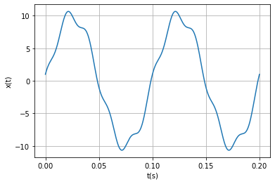
The test signal is $x(t)=10\sin(20\pi t)+\cos(100\pi t)$, sampled at $f_s=40f_{\tt{max}}$

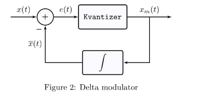
Block scheme of delta modulator is given as

enter image description here

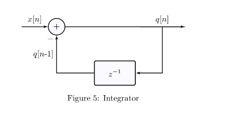
where integrator is given as

enter image description here

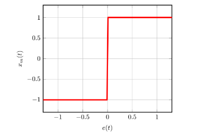
and characteristic of 1-bit quantizer is given as

enter image description here

This is my code where I tried to implement previous logic

import numpy as np
import matplotlib.pyplot as plt

fs = 40 * 50
duration = 0.2

t = np.linspace(0, duration, fs)
test_signal = 10 * np.sin(20 * np.pi * t) + np.cos(100 * np.pi * t)

plt.plot(t, test_signal)
plt.xlabel('t(s)')
plt.ylabel('x(t)')
plt.xticks([0, 5e-2, 0.1, 0.15, 0.2])
plt.grid(True)
plt.show()

def quantization(element):
  if element > 0:
    return 1
  else:
    return -1

x_m = []
integrator_state = 0

def delta_mod(x_t):

 for i in range(len(x_t)):
     if i == 0:
         x_m.append(quantization(x_t[0]))
         integrator_state = x_m[0]
     else:
         x = x_t[i] - integrator_state
         x_m.append(quantization(x))
         integrator_state = x_m[i]-integrator_state

 delta_mod(test_signal)

 
 plt.plot(t, x_m, drawstyle='steps-pre', label='x_m(t)')
 plt.xlabel('t(s)')
 plt.ylabel('x_m(t)')
 plt.yticks([-4,-2,0,2,4])

 plt.grid(True)

 plt.show()

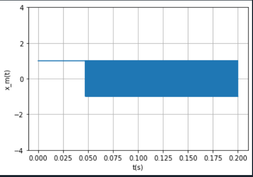
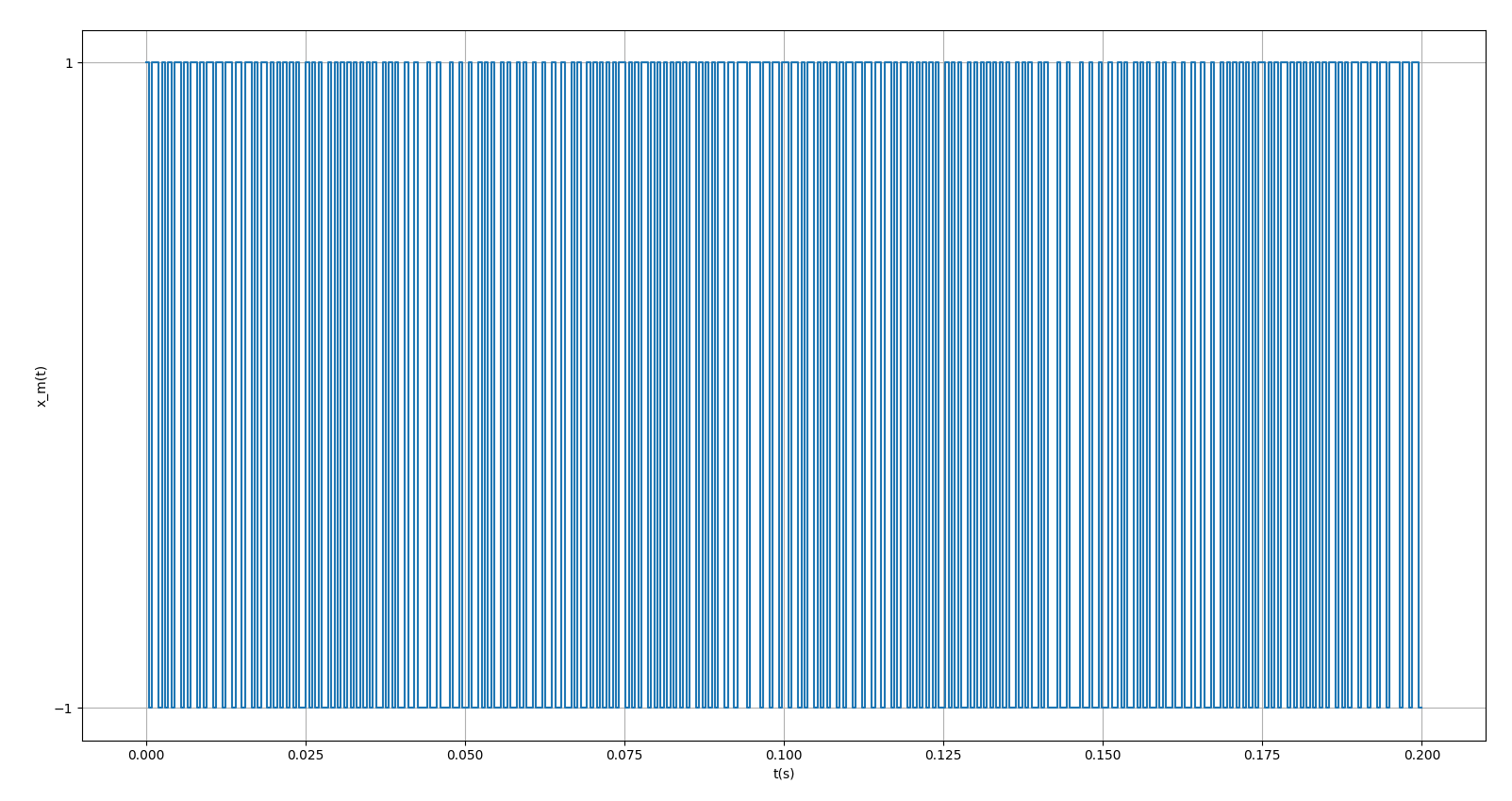
These are plots I get

enter image description here enter image description here

And these are plots that my proffesor got enter image description here
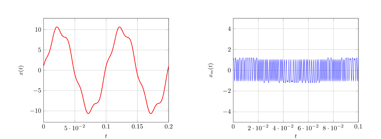
Does anyone know what am I doing wrong while trying to implement this logic.

$\endgroup$
5
  • $\begingroup$ x = x_t[i] + integrator_state Shouldn't this be a subtraction? $\endgroup$
    – MBaz
    Commented Jan 17 at 20:33
  • $\begingroup$ yeah sorry, I was trying different stuff and I forget to change to original code. I edited the question :) $\endgroup$
    – 3d014
    Commented Jan 17 at 20:50
  • 1
    $\begingroup$ I don't use numpy much, but should the linspace be generated as np.linspace(0, duration, fs*duration)? Also, integrator_state = x_m[i]-integrator_state seems backwards. $\endgroup$
    – MBaz
    Commented Jan 17 at 21:44
  • $\begingroup$ To point out, the integrator block diagram shown does not look correct, the integrator should be the delayed sample added to the next input to the accumulator (an accumulator), not subtracted as shown. The output of the integrator is then subtracted from the input. $\endgroup$ Commented Jan 18 at 5:30
  • $\begingroup$ Yeah, that's how it is represented in my lecture presentation but for some reason it is different in the task. However, thanks for pointing that out $\endgroup$
    – 3d014
    Commented Jan 18 at 6:05

1 Answer 1

1
$\begingroup$

First issue; your t is defined incorrectly. It should be: t = np.linspace(0, duration, int(duration * fs))

Secondly, you should replace your delta_mod function with the following corrected function:

def delta_mod(x_t):
    global integrator_state
    x_m.append(quantization(x_t[0]))
    integrator_state = x_m[0] 

    for i in range(1, len(x_t)):
        error = x_t[i] - integrator_state
        q_error = quantization(error)
        x_m.append(q_error)
        integrator_state += q_error

In the delta modulation loop, the integrator_state is supposed to accumulate the quantized values, but in your code, it's overwritten with just the last quantized value. Ignoring other minor issues and bad coding practices, these are the only significant issues I can see; indeed, it gives me the correct result (as far as I can tell).

x_m(t)

$\endgroup$
1
  • $\begingroup$ Thank you for your help. The problem I'm having is that if you watch his plot closely, it seems like his signal is not hard clipped on -1 and 1. So I'm wondering if I understood this quantizer characteristic the right way. $\endgroup$
    – 3d014
    Commented Jan 17 at 23:57

Your Answer

By clicking “Post Your Answer”, you agree to our terms of service and acknowledge you have read our privacy policy.

Not the answer you're looking for? Browse other questions tagged or ask your own question.